Sign In
Upload
Manuals
Brands
Honda Manuals
Motorcycle
Goldwing 1500
Honda Goldwing 1500 Manuals
Manuals and User Guides for Honda Goldwing 1500. We have
1
Honda Goldwing 1500 manual available for free PDF download: Service Manual
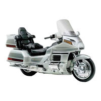
Honda Goldwing 1500 Service Manual (762 pages)
Brand:
Honda
| Category:
Motorcycle
| Size: 38.24 MB
Table of Contents
General Information
2
Important Safety Notice
3
Brake Dust
4
Brake Fluid Spilling
4
Warnings on Coolant
4
General Service Rules
4
Model Identification
5
Emission Control Systems
6
Source of Emissions
6
Crankcase Emission Control System
6
Exhaust Emission Control Systgems (Pulse Secondary Air Injection (PAIR) System)
7
Evaporative Emission Control System (California Model Only)
8
Noise Emission Control System
8
Emission Control Information Labels (USA Only)
9
Vacuum Hose Routing Diagram Label (California Model Only)
9
Metric Conversions
10
Honda NPS Part Numbers
11
Special Tools
12
Common Tools
13
Specifications
14
General Specifications
15
Cylinder Head Standards/Service Limits
17
Cylinder/Piston/Crankshaft Standards/Service Limits
17
Clutch Standards/Service Limits
18
Oil Pumps Standards/Service Limits
18
Transmission Standards/Service Limits
18
Cooling Standards/Service Limits
18
Final Drive Standards/Service Limits
19
Suspension Standards/Service Limits
19
Brakes Standards/Service Limits
19
Wheels/Tires Standards/Service Limits
20
Electrical Standards/Service Limits
20
Engine Torque Values
21
Frame Torque Values
22
Maintenance
24
Service Information
25
Torque Values
25
Lubrication Points
26
Service Access Guide
27
Vehicle View
27
Lubrication Diagram
29
Troubleshooting
30
Engine will Not Crank/Cranks but will Not Start
30
Afterfires, Explosions in Muffler
30
Oil Level too Low/High/Low Oil Pressure
30
Poor Handling
31
Engine Does Not Start or Is Hard to Start
31
Engine Lacks Power
32
Poor Performance at Low and Idle Speeds/At High Speed
33
Hydraulic Valve Adjuster System Troubleshooting
34
Noisy Tappet
34
Low Cylinder Compression
34
Maintenance Schedule
35
Engine Oil Level
36
Engine Oil and Filter Change
36
Oil Pressure Check
37
Final Drive Oil - Check/Change
38
Fuel Line Maintenance
39
Throttle Operation
39
Carburetor Starting Enrichment Valve
40
Carburetor Choke
41
Air Cleaner
41
Crankcase Breather Maintenance/Removal
42
Spark Plugs
42
Carburetor Synchronization
43
Carburetor Idle Speed
44
Cylinder Compression
44
Radiator Coolant
45
Cooling System Maintenance
46
Pulse Secondary Air Injection (PAIR) System Maintenance
47
Battery Maintenance
48
Brake Fluid
49
Brake Pad Wear
49
Front Brake Pad Wear Inspection
49
Brake System General Inspection
50
Brake Light Switch Maintenance
51
Headlight Aim Adjustment
51
Clutch System Maintenance
52
Clutch Fluid
52
Reverse Operation (a & SE Only)
53
Reverse Engagement Inspection
53
Side Stand Check
54
Suspension Maintenance
54
Air Pump Element (a & SE Only)
56
Air Driver (a & SE Only) Inspection
57
Desiccant Replacement
57
Cruise Valve Element (a & SE Only) Maintenance
58
Nuts, Bolts, Fasteners Checks
58
Wheels/Tires Maintenance
59
Recommended Tires and Pressures
59
Steering Head Bearings
60
Fuel System
61
Fuel System Service Information
62
Fuel System Diagram
63
Fuel System Location
64
Fuel System Circuit Diagram: a & SE Models
65
Fuel System Circuit Diagram: I Model
66
Fuel System Hoses and Tubes Routing/Connection
67
Fuel System Hoses and Tubes Routing/Connection California
68
Fuel System Troubleshooting
69
Engine Cranks but Won't Start/After Burning During Deceleration/Misfiring During Acceleration
69
Backfiring/Lean Mixture: Insufficient Fuel to Cylinders
69
Rich Mixture or Hesitation/Engine Idles Roughly, Stalls or Runs Poorly/Poor Performance (Driveability) and Poor Fuel Economy/Incorrect Fast Idle Speed
69
The Fuel Pump Does Not Operate for a few Seconds after the Ignition Switch Has Been Turned on
70
The Fuel Pump Operates Poorly
70
Fuel Indicator Light Does Not Come on Properly (a & SE Moedls Only)
70
The Fuel Gauge Does Not Operate Properly
71
Intake Air Shot Air (IASA) System
72
Carburetor Air Jet Control System
73
Poor Performance (Driveability) and Poor Fuel Economy
73
Intake Air Temperature (IAT) System and Accelerator Pump System Low Temperature Riding: Poor Performance (Driveability) and Poor Fuel Economy
74
Fuel Tank Removal
75
Fuel Tank Installation
76
Auto Fuel Valve Inspection
76
Fuel Filter
77
Air Cleaner Housing Removal/Installation
78
Sub Air Cleaner Housing
79
Carburetor Removal
79
Carburetor Separation
81
Carburetor Disassembly
83
Accelerator Pump
83
Vacuum Chamber
84
Float Chamber
84
Carburetor Assembly/Cleaning
86
Pilot Screw
86
Starting Enrichment (SE) Valve
88
Float Chamber Assembly
89
Float Level Inspection
89
Vacuum Chamber Assembly
90
Accelerator Pump Assembly
91
Carburetor Tubes/Hoses
94
Output Shaft
95
Carburetor Installation
96
Intake Manifold Removal
97
Intake Manifold Installation
98
Pilot Screw Adjustment
99
Idle Drop Procedure
99
Fuel Pump Operation Test
100
Fuel Pump Removal/Disassembly/Assembly
101
Fuel Pump Installation
102
Fuel Reserve Sensor/Indicator (a & SE Only)
103
Sensor Removal/Installation
103
Indicator Inspection
103
Fuel Level Sensor Removal/Operation Test
104
Float Level Sensor Inspection/Installation
104
Engine Control Module Inspection
106
Intake Air Shot Air (IASA) System Inspection
107
Intake Air Shot Air (IASA) Valve Inspection
108
IASA Check Valve Inspection
109
Carburetor Air Jet (CAJ) Control System Inspection
110
Carburetor Air Jet (CAJ) Solenoid Vlave Inspection
111
Intake Air Temperature (IAT) Sensor Inspection
112
Intake Air Temperature (IAT) Vacuum Actuator Inspection
113
IAT Thermal Vacuum Valve Inspection
113
IAT Check Valve Inspection
114
Hot Air Pipe
114
Pulse Secondary Air Injection (PAIR) System
115
PAIR Control Valve Removal/Installation
116
PAIR Check Valve Inspection
117
PAIR Solenoid Valve Inspection
118
Evaporative Emission (EVAP) Purge Control Valve Inspection
119
Canister
120
EVAP Carburetor Air Vent (CAV) Control Valve Inspection
120
Cruise Control (a & SE Only) - Service Information
121
Cruise Control (a & SE Only) - Sistem Location
122
Cruis Control System Circuit Diagram
123
Cruise Control Troubleshooting
124
Cruise Control Does Not Function at All
124
Cruise Control will Not Resume
126
Cruise Speed Fluctuates Excessively (more than 5 Mph) Immediately after Setting
127
Cruise Control Is Cancelled Accidently
128
Cruise Control Cannot be Cancelled
129
Auto Cruise Control Unit - System Inspection
130
Cruise Cancel Switches
132
Cruise Control Switches Inspection
134
Cruise Valve Relay - Continuity Inspection
134
Cruise Control Valve Unit Inspection
135
Cruise Actuator Inspection/Removal/Installation
136
Vacuum Accumulator Inspection
138
One-Way Valve Inspection
138
Vacuum Hoses Inspection
138
Cooling System
139
Cooling System Service Information/Torque Values
140
Coolant Course Diagram
141
Coolant System Location Diagram
141
Coolant Course Circuit Diagram
142
Coolant Course Troubleshooting
143
Engine Temperature too High/Low
143
Coolant Leaks
143
Temperature Gauge Not Operating Properly
143
Fan Motor Not Working
144
Coolant
145
Radiator Cap
145
Cooling System Pressure
145
Coolant Replacement
146
Radiator Removal
147
Radiator Installation
148
Cooling Fan Removal/Disassembly
149
Fan Motor Inspection/Assembly/Installation
150
Reserve Tank Removal/Installation
150
Thermostat, Carburetor Coolant Thermal Valve, Water Lines
151
Thermostat Removal/Inspection
151
Water Line Removal
151
Carburetor Coolant Thermal Valve Inspection
152
Carburetor Coolant Thermal Valve Installation
153
Water Pump
153
Mechanical Seal Inspection
153
Water Pump Inspection/Installation
154
Coolant Temparature Gauge Inspection
155
Temperature Sensor Removal/Inspection
155
Thermostatic Fan Motor Switch Inspection
156
Temperature Sensor Installation
156
Engine Removal/Installation
157
Engine Removal/Installation - Service Information
158
Engine Exploded Diagram/Torque Values
159
Engine Removal
160
Engine Installation
162
Cylinder Head/Exhaust System
164
Cylinder Head/Exhaust System - Service Information/Torque Values
165
Cylinder Head/Exhaust System - Troubleshooting
166
Timing Belt Removal
167
Belt Inspection
168
Camshaft/Rocker Arm Removal
169
Camshaft Inspection
170
Camshaft Holder Disassembly
171
Rocker Arm Shaft Inspection
172
Rocker Arm/Eccentric Spindle Inspection
172
Hydraulic Valve Adjuster Inspection
172
Cylinder Head Removal
173
Cylinder Head Disassembly/Inspection
174
Valve Spring Inspection
175
Valve and Guide Inspection
175
Valve Guide Replacement
176
Valve Seat Inspection/Refacing
177
Valve Seat Cutters
178
Cylinder Head Assembly/Installation
180
Camshaft Holder Assembly/Installation
182
Timing Belt Installation
185
Hydraulic Valve Adjuster Shim Selection
187
Exhaust Pipe/Muffler
191
Chamber Protector
191
Exhaust Pipe Protectors
192
Exhsust Pipe Protector Lid Opener
194
Opener Cable Adjustment
194
Heat Protectors
195
Exhaust Pipe
195
Muffler
196
Exhaust Chamber
196
Crankshaft/Piston
197
Crankshaft/Piston - Service Information/Torque Values
198
Crankshaft/Piston Troubleshooting
201
Front Engine Cover Removal
202
Bearing Holder (Output Shaft)
203
Rear Case Cover
203
Cover Bearing
204
Scavenging Pump Removal/Disassembly/Inspection
206
Scavenging Pump Assembly
207
Scavenging Pump Installation
208
Oil Strainer and Main Oil Pump Removal
210
Ol Strainer Cleaning
210
Relief Valve Check
210
Main Oil Pump Disassembly
210
Main Oil Pump Assembly
211
Oil Strainer and Main Oil Pump Installation
212
Piston/Connecting Rod Removal
213
Side Clearance Inspections
213
Piston/Ring/Rod Inspection
213
Cylinder Inspection
216
Crankpin Bearing
217
Oil Clearance Inspection
217
Bearing Selection
218
Bearing Installation
219
Piston/Connecting Rod Installation
219
Connecting Rod Selection
219
Crankshaft Removal/Inspection
223
Main Journal Bearing - Oil Clearance Inspection
224
Main Journal Bearing Selection
225
Bearing Insert Thickness, MM (In)
226
Main Journal Bearing Installation
226
Crankshaft Installation
226
Front Engine Cover Installation
228
Rear Case Cover Installation
229
Clutch
232
Clutch - Service Information/Torque Values
233
Clutch Diagram
234
Clutch Troubleshooting
235
Clutch Fluid Replacement/Air Bleeding
236
Clutch Master Cylinder Disassembly
237
Clutch Master Cylinder Inspection
238
Clutch Master Cylinder Assembly/Installation
239
Clutch Slave Sylinder Disassembly/Assembly
240
Clutch Disassembly/Inspection
241
Clutch Assembly
245
Transmission
250
Transmission - Service Information
251
Transmission Diagrams
252
Transmission Torque Values
253
Transmission Troubleshooting
254
Gearshift Linkage Removal
255
Gearshift Linkage Inspection/Installation
256
Crankcase Separation
258
Transmission Disassembly
259
Transmission Inspection
261
Shift Drum Inspection
261
Shift Fork/Shift Fork Shaft Inspection
261
Transmission Gear Inspection
262
Shaft Inspection
262
Transmission Assembly
263
Crankcase Assembly
267
Crankcase Torque Values
270
Primary Drive/Driven Gears Removal
271
Boss Bearing Replacement
271
Primary Drive Gear Installation
272
Output Shaft Removal
274
Output Shaft Disassembly/Inspection
275
Output Shaft Assembly
276
Final Drive
280
Final Drive - Service Information/Torque Values
281
Final Drive - Troubleshooting
282
Gear Case Removal
283
Drive Shaft Removal/Disassembly
283
Drive Shaft Assembly
284
Universal Joint Removal/Installation
284
Gear Case Disassembly
285
Backlash Inspection
285
Ring Gear Spacer, Ring Gear Removal
285
Gear Tooth Contact Pattern Check
287
Ring Gear Bearing/Spacer Replacement
288
Pinion Spacer Replacement
289
Case Bearing Replacement
291
Gear Case Assembly
293
Gear Case Installation
296
Frame/Suspension
297
Frame/Suspension - Service Information
298
Frame/Suspension Diagram/Torque Values
299
Frame/Suspension - System Location
300
Frame/Suspension - Circuit Diagram (a & SE Only)
301
Frame/Suspension Troubleshooting
302
Wobble or Vibration
302
Soft/Hard Suspension
302
Suspension Noise
302
Frame/Suspension Troubleshooting (a & SE Only)
303
Ride and Level Control Pressure will Not Increase
303
Suspension System will Not Decrease Pressure, but will Increase Pressure
305
The Auxiliary Air Pressure Does Not Work, but the Ride and Level Control Works
305
Air Compressor System Works, but LCD Unit Display Does Not Work Properly
306
Fork Legs Removal
307
Fork Slider Needle Bearing Replacement
307
Fork Legs Disassembly
308
Fork Legs Inspection
310
Anti-Dive Case
311
Fork Legs Assembly
312
Fork Legs Installation
315
Shock Absorbers Removal
316
Rubber Bushing Inspection
317
Shock Absorbers Disassembly/Assembly
317
Oil Seal Replacement
318
Shock Absorbers Installation
321
Swing Arm Removal
322
Pivot Bearing Replacement
323
Swing Arm Installation
325
On-Board Air Compressor System
327
Air Hoses Inspection (a & SE Only)
327
Air Pump Removal
327
Drier Disassembly/Assembly
328
Air Pump Inspection/Installation
328
Air Distributor Removal
329
Solenoid Valve Inspection
329
Air Distributor Passage Cleaning
330
Air Pressure Sensor Inspection
330
Air Pressure Control Switch Inspection
331
Air Pump Relay (Relay 5 in the Relay Box)
332
Operation/Continuity/Wiring Inspection
332
Handlebar Removal/Installation
333
Steering Stem Removal
337
Bottom Bearing Replacement
338
Bearing Race Replacement
339
Steering Stem Installation
340
Fairing/Body Components
343
Table of Contents
343
Fairing/Body Components - Service Information
344
Fairin ,Oay Components
344
Service Information 13~2
344
Windshield Replacement
345
Center Fresh Air Visor (SE Only) Removal/Installation
346
Windshield Lever Replacement/Adjustment (a & SE Only)
346
Fairing
348
Seat
350
Rear/Front Seat Cover
350
Left Fairing Pocket
350
Right Fairing Pocket
351
Ignition Switch Cover
351
Top Inner Cover
351
Top Compartment
351
Instrument Panel
353
Fairing Front Cover
353
Under Cover
353
Radiator Shroud
353
Fairing Lower Cover/Inner Covers
354
Air Ducts
355
Trunk/Saddlebags
356
Trunk Lower Cover
357
Trunk
357
Trunk Opener
358
Saddlebag/Saddlebag Lower Cover
359
Front Fender
360
Rear Fender
361
Adjustable Passenger Footrests (SE Only)
362
Footrests (SE)
362
Footrest Remote Lever
363
Remote Cable Adjustment
363
Footrests (a & 1 Only)
364
Brakes
365
Brakes - Service Information/System Location
366
Brakes - Exploded Diagram/Torque Values
367
Brakes Troubleshooting
368
Brake Fluid Replacement/Air Bleeding
369
Brake Lever System Fluid Replacement (Front/Right)
369
Air Bleeding (Brake Lever System)
370
Air Bleeding (Brake Pedal System)
371
Brake Pad Replacement
371
Brake Disc Inspection
375
Front Master Cylinder Removal/Disassembly
376
Front Master Cylinder Inspection/Assembly
377
Front Master Cylinder Installation
378
Rear Master Cylinder Removal
378
Rear Master Cylinder Disassembly
379
Rear Master Cylinder Inspection
380
Rear Master Cylinder Installation
381
Front Brake Caliper Removal/Disassembly/Inspection
383
Front Brake Caliper Assembly/Installation
384
Front Brake Caliper Removal/Disassembly
385
Front Brake Caliper Inspection/Assembly/Installation
386
Brake Pedal Removal/Installation
387
Metal Brake Line Removal
388
Metal Brake Line Installation
390
Wheels/Tires
391
Wheels/Tires - Service Information
392
Wheels/Tires - Diagram/Torque Values
393
Wheels/Tires - Troubleshooting
394
Front Wheel Removal
395
Wheel Bearing Inspection
396
Wheel Rim Runout Inspection
396
Axle Inspection
396
Wheel Disassembly
396
Bearing Replacement
397
Wheel Assembly
397
Front Wheel Installation
398
Rear Wheel Removal
400
Trunk/Saddlebars - Removal with a Helper
400
Trunk/Saddlebars - Removal Without a Helper
401
Rear Wheel Inspection/Disassembly
403
Rear Wheel Installation
406
Trunk/Saddbebag - Installation with a Helper
408
Trunk/Saddbebag - Installation Without a Helper
409
Wheel Balancing
410
Ignition
411
Ignition - Service Information/System Location
412
Ignition - Circuit Diagram: a & SE Models
413
Ignition - Circuit Diagram: I Model
414
Ignition Troubleshooting
415
Engine Doesn't Start or Is Hard to Start
415
Engine Starts, but Runs Rough at Low Engine Speed (below 2,000 Rpm)
416
Poor Performance (Driveability) and Poor Economy of Fuel
417
Engine Starts, but Side Stand Switch Does Not Function
417
Rich Mixture or Hesitation
417
Engine Control Module - System Inspection
418
Ignition Coil Inspection/Removal
419
Ignition Coil Installation
420
Ignition Pulse Generator Inspection
421
Ignition Pulse Generator Removal/Installation
422
Ignition Pulse Rotor Removal/Installation
422
Gear Position Switch Inspection/Removal/Installation
424
Side Stand Switch Inspection/Removal/Installation
425
Engine Coolant Temperature Sensor Inspection/Removal
426
Engine Coolant Temperature Sensor Installation
427
Engine Stop Switch
427
Ignition Timing
428
Idle Timing Inspection
428
Vacuum Advance Inspection
428
Gear Position Switch Timing Shift Inspection
429
Engine Coolant Temperature Sensor Timing Shift Inspection
430
Charging
431
Charging - Service Information/Torque
432
Charging - System Location
433
Charging - Circuit Diagram
434
Charging Troubleshooting
435
Abnormal Engine Noise (Gear Noise)
435
Battery Discharging/Overcharging
435
Battery Removal
437
Specific Gravity
437
Battery Charging/Installation
438
Leakage Test
439
Charging System Operation
439
Regulated Charging Output Table
439
Wire Harness Inspection
440
Alternator and Regulator/Rectifier Removal
440
Alternator and Regulator/Rectifier Disassembly
441
Condenser Inspection
442
Rotor Coil Inspection
442
Rotor Bearing/Brush Length Inspection
443
Stator Coil/Fan Guide Inspection
444
Rotor Bearing/Oil Seal Replacement
445
Alternator and Regulator/Rectifier Assembly
446
Alternator and Regulator/Rectifier Installation
447
Alternator Drive/Driven Gears Removal
449
Case Bering Replacement
449
Alternator Drive/Driven Gear Disassemble/Inspection
450
Alternator Drive/Driven Gear Assembly
451
Alternator Drive/Driven Gear Installation
453
Starter/Reverse
454
Starter/Reverse - Service Information (a & SE Models)/Torque Values
455
Starter/Reverse - Circuit Diagram (a & SE Only)
456
Starter/Reverse - System Location
457
Starting System Diagram
457
Starter/Reverse - Troubleshooting (a & SE Models)
458
The Starter/Reverse Motor for Starting Does Not Turn
458
The Starter/Revers Motor Turns in Neurtral Position, but Does Not Turn in Gear with the Side Stand up and the Clutch Lever Pulled in
460
Starter Motor Turns Engine Slowly/Turns, but Engine Does Not Turn
460
Starter Motor and Engine Turn, but Engine Does Not Start
460
The Starter/Reverse Motor Does Not Turn for Reverse
461
The Reverse Speed Is Slow (below 1.0 Km/H on a Flat Road)
462
The Reverse System Works, but the Motor Does Not Stop if It Is Overloaded more than Three Seconds
463
Reverse Operation Is Rough, or Reverse Motor Runs Poorly
463
Continues Operating in Reverse Even if the Starter/Reverse Switch Is Free
463
Stops Immediately When Reverse Operation Is Initiated
464
The Motorcycle Lunges at the Beginning of Reverse Operation
464
The Reverse System Operates before Being Properly Selected
465
During Reverse Operation the Headlight Goes Out/The Motor Idles
465
Transmission Is Hard to Shift with Reverse Lever in off Position/During Forward Operation the Rear Wheel Is Locked Suddenly
465
After Shifting into Reverse, the Transmission Is Easy to Shift/Hard to Shift to Reverse
465
Starter/Reverse Motor (a & SE Models) Removal/Disassembly
466
Reduction Gear Case Disassembly/Inspection
468
Reduction Gear Case Assembly
470
Motor Assembly
472
Starter/Revers Motor Installation
474
Starter Clutch (a & SE Models) Removal/Inspection/Disassembly
475
Starter Clutch (a & SE Models) Assembly
476
Starter Clutch (a & SE Models) Installation
477
Fuel Pump Shut-Off (Band Angle) Sensor (a & SE Models) Inspection/Installation
478
Starter Relay Switch a ( a & SE Models) Operation and Continuity Inspection
479
Starter Relay Switch B (a & SE Models)
479
Relay Box (a & SE Models) Operation and Continuity Inspection
480
Diode Assembly (a & SE Models) - Continuity Inspection
481
Reverse Switch (a & SE Models) Inspection/Removal
481
Reverse Switch (a & SE Models) Installation
482
Starter/Reverse Switch (a & SE Models) Inspection
482
Clutch Switch (a & SE Models) Inspection
483
Reverse System (a & SE Models) Cable Replacement
483
Reverse Shift System Removal
484
Shift Drum Lock System Removal/Bearing Replacement
486
Shift Drum Lock System Installation
488
Reverse Shift System Installation
489
Reverse Control Unit (a & SE Models) - System Inspection
492
Speed Limiter Relay Line Inspection
494
Starter Relay Regulator (a & SE Models) - Wiring Inspection
494
Regulated Voltage Inspection
495
Reverse Resistor Assembly (a & SE Models) Removal
495
Reverse Resistor Assembly (a & SE Models) Inspection/Installation
496
Power Control Relay (a & SE Models) Operation Inspection/Continuity Inspection
496
Speed Limiter Relay (a & SE Models) Operatin Inspection/Continuity Inspection
497
Reverse Lever Switch (a & SE Models) Inspection
497
Starter/Reverse - Service Information (I Model)/System Location
498
Starter/Reverse Circuit Diagram
499
Starter/Reverse Troubleshooting
500
Starter Motor (I Model) Removal/Reduction Gear Case Disassembly/Inspection
502
Starter Motor (I Model) Installation
504
Diode (I Model)
504
Lights/Switches/Instruments
506
Lightslswitchesllnstruments
507
Service Information 19~2
507
Lights/Switches/Instruments - Circuit Diagram (a Model)
508
Lights/Switches/Instruments - Circuit Diagram (SE Model)
509
Self Cancelling Turn Signal System Diagram (a & SE Only)
511
Lights/Switches/Instruments Troubleshooting
512
Troubleshooting 19~5
512
Turn Signal Do Not Operate
513
Turn Signals Do Not Cancel Automatically/Manually (a & SE Only)
514
On Parking, When the Front Wheel Is Turned Slowly from Left to Right, Turn Signal Is Cancelled (a & SE Only)
515
Turn Signal Lights Do Not Come on
515
Hazard System Does Not Operate
515
Liquid Crystal Display (LCD) Does Not Appear Upon Turning the Ignition Switch to ACC, on or P (a & SE Only)
516
Clock Displays, but Air Pressure Display will Not Come on When the Check Switch Is Depressed with the Motorcycle Stopped (a & SE Only)
516
Air Pressure Display Doesn't Change, but the On-Board Air Compressor System Is Operating Properly (a & SE Only)
517
Radio and Cassette Deck Display Does Not Appear on the LCD Unit (a & SE Only)
518
Headlight/Position Light Removal
519
Bulb Replacement
519
Headlight Installation
520
Turn Signals/Brake Lights
520
Front Turn Signal/Position Lights
520
Rear Turn Signal/Brake and Taillights (Trunk)
521
Brake and Taillights (Saddlebags)
521
License/Accessory Light
522
Instruments Removal/Bulb Replacement
523
Speed Sensor Inspection (a & SE Only)
523
Electric Tachometer Inspection/Disassembly
524
Instruments Assembly/Installation
527
Ignition Switch Inspection/Removal
527
Ignition Switch Disassembly/Assembly/Installation
528
Left Handlebar Switches Inspection
529
Brake Light Switches
530
Oil Pressure Switch Inspection
530
Relay Box Continuity Inspection
531
Parking Diode Inspection (a & SE Only)
531
Self Cancelling Turn Signal System
532
Turn Signal Cancel Control Unit Inspection (a & SE Only)
532
Turn Signal Relay Inspection
533
Turn Signal Cancel Control Unit Removal/Installation
534
Hazard Relay Inspection
535
Horn Inspection/Replacement
535
High Mount Accessory Light Replacement (SE Only)
536
Accessory Light Control Unit (SE Only)
536
Cornering Light Replacement (SE Only) Replacement
537
Audio
538
Audio - Service Information
539
Audio - Circuit Diagram (a & SE Models)
540
Audio - Circuit Diagram (SE Model)
541
Audio - Circuit Diagram (I Model)
542
Audio - System Location Diagram
543
Audio System Troubleshooting
545
Speakers (Optional Headsets): no Sound
545
Radio and Cassette Deck Work, but Do Not Search or Mute with the Muting/Search Switch
546
Weak (or Noisy) Reception
546
Radio Cuts out and Loses Memory While Riding
547
The Radio and Cassette Deck Display Does Not Appear on the LCD Unit (a and SE Models)
547
AVC (Auto Volume Control) Does Not Work at All (a and SE Models)
548
Unsatisfactory Cassette Deck Sound (a and SE Models)
548
Radio Works, but Cassette Deck Does Not Work at All (a and SE Models)
548
CB Transceiver Does Not Turn on or Channels Are Not Memorized
549
Channel Cannot be Changed
549
CB Output Cannot be Transmitted
550
CB Output Can be Transmitted, but CB Signals Cannot be Modulated
550
No Reception or no Radio and Cassette Sound
551
Communication Distance Is Short
552
Too Much Noise or Bad Sensitivity
552
Radio/Cassette Sound Does Not Mute During CB Signal Transmission or Reception
553
CB Output Cannot be Transmitted or CB Signals Cannot be Modulated with the Radio and Cassette Deck Turned off
553
Speaker Removal/Inspection/Installation
554
Muting/Search Switch Inspection
554
CB Switch/Fader Control (SE Only)
555
Antenna Removal/Inspection
556
Antenna Base Replacement
556
Radio and Cassette Deck
557
Main Wire Harness Check
557
Headset Junction Wire Check
560
AUX Sub-Cord Check
560
CB Transceiver
561
Index
564
Electrical Troubleshooting Manual (Etm)/How to Use this Manual
567
ETM - Symbols
568
ETM - How to Use Circuit Schematics
572
ETM - How to Use this Manual (Cont.)
575
Troubleshooting Tests
577
Troubleshooting Precautions
581
Fuse Information: Asp and SE
582
Fuse Information: Int
583
LCD Unit Display
584
Power Distribution: Asp and SE - Circuit Schematic
586
Power Distribution: Int - Circuit Schematic
592
Ground Distribution: G100, G102, G103, and G104 (Asp & SE) - Circuit Schematic
596
Ground Distribution: G100, G102, G103, and G104 (Int) - Circuit Schematic
602
Engine Control System: Asp and SE - Circuit Schematic
608
Engine Control System: Int - Circuit Schematic
612
Engine Control System: How the Circuit Works/Troubleshooting
615
Isolation Procedure 1
616
Isolation Procedure 2
617
Engine Control System - Troubleshooting Tests
619
Starting System: Asp and SE - Circuit Schematic
622
Starting System: Int - Circuit Schematic
624
Starting System: How the Circuit Works
626
Starting System Troubleshooting - Asp and SE Models/Int Models
627
Starting System Troubleshooting Tests
628
Charging System - Circuit Schematic
634
Charging System: How the Circuit Works/Troubeshooting
635
Radiator Fans Circuit Schematic
636
Rerverse System Circuit Schematic
638
Rerverse System: How the Circuit Works
641
Reverse System Check/Reset
641
Reverse System Troubleshooting
642
Self-Test A: Static Measurement
644
Self-Test B: Continuity Test
645
Self-Test C: Reverse Lever Switch
646
Self-Test D: Side Stand Switch
646
Self-Test E: Gear Position Switch Test
646
Self-Test F: Power Relay Control Test
647
Self-Test G: Speed Limiter Relay Test
647
Self-Test H: Reverse Resistors
647
Cruise Control Circuit Schematic
648
Cruise Control - How the Circuit Works
652
Cruise Control Troubleshooting (ETM)
653
Isolation Procedure
654
Test A: Cruis Unit Power
657
Test B: Cruise Unit Cancel Input Test
657
Test C: Cruise Relay Valve Input Test
657
Test D: Clutch Cancel Input Test
657
Test E: SET/DECEL Switch Countinuity Check
658
Test G: Vacuum Valve Control Check
658
Test H: Vent Valve Continuity Check
658
Test I: Cruise SET Indicator Control Test
659
Test J: Cruise on Indicator Control Test
659
Test K: Speed Signal Input Test
659
Test L: Cruise Control Actuator Vacuum Input Test
660
Test M: Cruise Control Actuator Vent Input Test
660
Horn: Asp and SE Circuit Schematic
662
Horn: Int Circuit Schematic
663
Clock: Asp and SE Circuit Schematic
664
Automatic Level Control Circuit Schematic
666
Low Fuel and Oil Pressure Warning System: Asp and SE Circuit Schematic
668
Low Fuel and Oil Pressure Warning System: Int Circuit Schematic
669
Indicators: Asp and SE Circuit Schematic
670
Indicators: Int Circuit Schematic
672
Instrument Panel: Gauges, Illumination Lights (Asp and SE) Circuit Schematic
674
Speed Sensor Circuit (Wheel Speed) Curcuit Schematic
676
Speed Sensor Circuit (Crankshaft Speed) Curcuit Schematic
677
Instrument Panel: Gauges, Illumination Lights (Int) Circuit Schematic
678
Headlights: Asp and SE Circuit Schematic
680
Headlights: Int Circuit Schematic
682
Marker Lights: Fairing and Trunk Circuit Schematic
684
Marker Lights: Saddlebags Circuit Schematic
686
Cornering Lights: Asp and SE Circuit Schematic
687
Cornering Lights: Int Circuit Schematic
688
Handlerbar Switch Illumination Circuit Schematic
689
Turn Signal, Hazard and Position Lights: Asp and SE Circuit Schematic
690
Turn Signal, Hazard and Position Lights: Int Circuit Schematic
692
Turn Signal, Hazard and Position Lights: All Models Circuit Schematic
694
Tail, Parking, and License Plate Lights: Asp and SE Circuit Schematic
696
Tail, Parking, and License Plate Lights: Int Circuit Schematic
698
Brake Lights: Asp and SE Circuit Schematic
700
Brake Lights: Int Circuit Schematic
701
Trunk Light Circuit Schematic
702
Accessory Light Circuit Schematic
703
Spoiler Brake/Taillight: SE Only Circuit Schematic
704
Radio and Cassette: Asp and SE Circuit Schematic
706
Without/With Rear Speakers (ASP) Circuit Schematic
707
Radio and Cassette: Asp and SE Circuit Schematic (Cont.)
708
Radio/Clock: Int Circuit Schematic
712
Radio System: How the Circuit Works
717
Radio Troubleshooting
718
Test A: Radio Does Nop Operate and Radio Information Does Not Appear on Display
720
Test B: Radio Volume Does Not Vary with Vehicle Speed (Asp and SE Models)
720
Test C: Radio Operates but Radio Information Does Not Display Properly (Asp and SE Models)
720
Test D: One or both LH Front or RH Front Speakers Are Inoperative (Asp and Int Models Without Rear Speakers)
720
Test E: One or more Speakers Are Inoperative (ASP Model with Rear Speakers)
721
Test F: One or more Speakers Do Not Operate Normally (SE Model Only)
721
Test G: Fader Does Not Operate Normally or One Side Is Much Louder (SE Model Only)
722
Test H: Passenger Headset Is Inoperative but Driver Headset Is OK (Without Passenger Controller)
722
Test I: Driver Headset Is Inoperative but Passenger Headset Is OK
723
Test J: Driver and Passenger Headsets Are Inoperative
723
Tesk K: Passenger Headset Is Inoperative but Driver Headset Is OK (with Passenger Controller)
724
Test L: MUTE, TUNE-UP, TUNE-DOWN Search Functions Do Not Operate
724
Test M: TUNE-UP or TUNE-DOWN Functions Do Not Work from Passenger Controller
725
Test N: Auxiliary CD or Tape Player Does Not Operate (Int Model)
725
Citizen Band Radio: Asp Circuit Schematic
726
Citizen Band Radio: Int Circuit Schematic
728
Citizen Band Radio: SE Circuit Schematic
730
Citizen Band Radio: How the Circuit Works/Troubleshooting
732
Test A: CB Radio Does Not Operate and Display Is Blank
733
Test B: CB Receives but Does Not Transmit
733
Test C: CB Transceiver Input/Output Test
733
Test D: CB Does Not Transmit And/Or Channel Select Does Not Operate from Passenger Switch
734
Test E: CB Channel Select Does Not Operate but Transmit Function Operates
734
Component Location Index
736
Section 12: Component Location Photographs
744
Component Index
756
Advertisement
Advertisement
Related Products
Honda 1998 CD250U
Honda 1989 CBR1000F
Honda 1985 CBX550 Four
Honda 1969 ST 50 E
Honda 1986 CBX750F
Honda 1985 CBX750F
Honda 1988 Z50R
Honda 1998 VT750CD3
Honda 1985 XLV750R
Honda 1999 VT750CD2 Shadow Deluxe
Honda Categories
Motorcycle
Automobile
Lawn Mower
Offroad Vehicle
Engine
More Honda Manuals
Login
Sign In
OR
Sign in with Facebook
Sign in with Google
Upload manual
Upload from disk
Upload from URL