Sign In
Upload
Manuals
Brands
Honda Manuals
Automobile
CR-V 2000
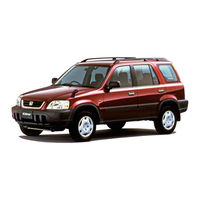
Honda CR-V 2000 Manuals
Manuals and User Guides for Honda CR-V 2000. We have
4
Honda CR-V 2000 manuals available for free PDF download: Service Manual, Owner's Manual, Online Reference Owner's Manual
Honda CR-V 2000 Service Manual (1398 pages)
Brand:
Honda
| Category:
Automobile
| Size: 42.97 MB
Table of Contents
Contents
2
Special Information
2
General Information
3
Table of Contents
3
Chassis and Paint Codes
4
Vehicle Identification Number
4
Engine Number
4
Transmission Number
4
U.S. 1998 Model
5
U.s.
6
1999 Model
6
U.S. 2000 Model
7
Canada 1997 Model
8
Canada 1998 Model
9
Canada 1999 Model
10
Canada 2000 Model
11
Identification Number Locations
12
Vehicle Identification Number (VIN)
12
Transmission Number (Manual)
12
Transmission Number (Automatic)
12
Warning/Caution Label Locations
13
Cable Reel Caution
13
Driver Module Danger
13
Driver Module Warning
13
Srs Warning Ihoodi
14
STEERING COLUMN NOTICE Ihoodi
14
Monitor Notice
14
Front Seat Passenger Airbag Module Danger
15
Passenger Information
15
Srs Information
15
Front Passenger Airbag Warning
15
Under-Hood Emissions Control Label
17
Emission Group Identification
17
Engine and Evaporative Families
17
Lift and Support Points
21
Lift and Safety Stands
21
Floor Jack
22
Towing
23
Service Precautions
24
Parts Marking Locations
24
Precautions for Real-Time 4WD
25
Specifications
26
Standards and Service Limits
27
Engine Electrical
27
Cylinder Head/Valve Train
27
Engine Block
28
Engine Lubrication
29
Cooling
29
Fuel and Emissions
29
Clutch
30
Manual Transmission
30
Suspension
36
Brakes
36
Air Conditioning
36
Design Specifications
37
Body Specifications
39
Maintenance
40
Lubrication Points
41
Api Service Label
41
Api Certification Seal
41
Maintenance Schedule
43
Normal Conditions
43
Severe Conditions
45
Special Tools
52
Starting System
53
Component Location Index
53
Circuit Diagram
54
Starter Test
55
Recommended Procedure
55
Alternate Procedure
55
Check the Starter Engagement
55
Starter Solenoid Test
56
Check for Wear and Damage
56
Check Cranking Voltage and Current Draw
56
Check Cranking Rpm
56
Starter Replacement
57
Field Winding Test
57
Starter Overhaul
58
Brush Inspection
59
Overrunning Clutch Inspection
59
Armature Inspection and Test
60
Brush Holder Test
62
Starter Reassembly
62
Performance Test
63
Ignition Timing Control System
64
Component Location Index
64
Circuit Diagram
65
Ignition Timing Inspection and Setting
66
Distributor Replacement
67
Distributor Overhaul
68
Ignition Control Module (Lcm) Input Test
69
Ignition Coil Test
70
Ignition Wire Inspection and Test
70
Spark Plug Inspection
71
Electrode Gap
71
Component Location Index
72
Circuit Diagram
73
Charging System Light Test
74
Troubleshooting
74
Alternator Replacement
80
Alternator Overhaul
81
Rectifier Test
82
Alternator Brush Inspection
82
Rotor Slip Ring Test
83
Stator Test
83
Alternator Belt Inspection and Adjustment
84
Deflection Method
84
Belt Tension Gauge Method
84
Component Location Index
86
Circuit Diagram
87
Control Unit Input Test
88
Disconnect the 14P Connector from the Control Unit
89
Main Switch Test/Replacement
90
Set/Resume Switch Testl Replacement
90
Actuator Test
91
Actuator Replacement
92
Actuator Test
92
Actuator Cable Adjustment
93
Clutch Switch Test
93
Brake Switch Test
94
Actuator Solenoid Test
94
Actuator Disassembly
95
Engine
96
Engine Removal/Installation
97
Special Tools
115
Valve Clearance Adjustment
116
Valve Seals
118
Replacement (Cylinder Head Removal Not Required)
118
Exhaust Valve Seals
119
Crankshaft Pulley and Pulley Bolt
120
Replacement
120
Illustrated Index
121
Inspection
122
Tension Adjustment
122
Removal
123
Replacement
126
Cylinder Head Illustrated Index
127
Removal
128
Warpage
128
Installation
128
Camshafts
135
Inspection
135
Valves. Valve Springs and Valve Seals
136
Removal
136
Valves, Valve Springs and Valve Seals
137
Valve Guides
138
Valve Movement
138
Replacement
138
Reaming
140
Warpage
140
Valve Seats
141
Reconditioning
141
Special Tools
148
Illustrated Index
149
Flywheel and Drive Plate
151
Replacement
151
Connecting Rod and Crankshaft
152
End Play
152
Main Bearings
153
Clearance
153
Selection
154
Connecting Rod Bearings
154
Clearance
154
Pistons and Crankshaft
155
Selection
155
Removal
155
Inspection
157
Pistons
158
Inspection
158
Cylinder Block
159
Inspection
159
Piston Pins Removal
160
Connecting Rods
160
Piston Rings
163
End Gap
163
Ring-To-Groove Clearance
163
Replacement
164
Alignment
164
Crankshaft Oil Seal Installation
165
Pistons Installation
166
Crankshaft Installation
166
Oil Seals
169
Installation
169
Special Tools
172
Illustrated Index
173
Engine Oil
174
Inspection
174
Replacement
174
Oil Filter
175
Replacement
175
Oil Pressure Switch
177
Testing
177
Oil Pump
178
Overhaul
178
Removal/Inspection/Installation
179
Intake Manifold/Exhaust System
182
Illustrated Index
190
Radiator
192
Replacement
192
Engine Coolant Refilling and Bleeding
193
Cap Testing
195
Testing
195
Thermostat
196
Replacement
196
Testing
197
Water Pump
198
Illustrated Index
198
Inspection
199
Replacement
199
Fan Control
200
Component Location Index
200
Circuit Diagram
201
Fan Motor Testing
202
Radiator Fan Switch Testing
202
Coolant Temperature Gauge
203
Gauge Testing
203
Coolant Temperature Sending Unit Testing
203
Electrical Connections
218
Symptom Chart
266
Probable Cause List
266
ECM/PCM Data
267
Powertrain Control Module Terminal Arrangement
269
PGM-FI System
282
Engine Control Module (Ecm)
282
Powertrain Control Module (Pcm)
282
PCM Fail-Safe/Back-Up Functions
283
Fuel Cut-Off Control
283
Compressor Clutch Relay
283
Engine Coolant Temperature (ECT) Sensor
301
Throttle Position
305
Primary Heated Oxygen Sensor (Primary H02S) (Sensor 1)
312
Random Misfire
328
Misfire Detected in One Cylinder
329
Idle Control System
351
Idle Air Control (Lac) Valve
354
Air Conditioning Signal
357
Power Steering Pressure (PSP) Switch Signal
364
Brake Switch Signal
368
Fast Idle Thermo Valve (Aft)
370
Idle Speed Setting
371
Fuel Supply System
373
Fuel Lines
373
Fuel Tube/Quick-Connect Fittings
377
Fuel Pressure
380
Fuel Injectors
381
Fuel Pressure Regulator
383
Fuel Filter
384
Fuel Pump
385
Fuel Gauge
386
Fuel Gauge Sending Unit
387
Low Fuel Indicator System
388
Indicator Light Testing
388
PGM-FI Main Relay
389
Intake Air System
395
Air Cleaner
396
Throttle Cable
396
Air Cleaner Element Replacement
396
Throttle Body
398
Emission Control System
401
Tailpipe Emission
401
Three Way Catalytic Converter (TWC)
401
Positive Crankcase Ventilation (PCV) System
403
Evaporative Emission (EVAP) Controls
405
Transaxle
427
Clutch Master Cylinder
432
Slave Cylinder
433
Pressure Plate
434
Clutch Disc
435
Flywheel
436
Clutch Disc, Pressure Plate
437
Release Bearing
438
Back-Up Light Switch
442
Transmission Fluid
442
Transfer Assembly
443
Shift Arm Cover/Shift Arm Shaft Assembly
457
Shift Ann Cover Assembly
457
Clearance Inspection
458
Reverse Shift Holder
459
Shift Fork Assembly
460
Mainshaft Assembly
462
Countershaft Assembly
467
Synchro Sleeve, Synchro Hub
475
Synchro Ring, Gear
476
Final Driven Gear Replacement
478
Tapered Roller Bearing Replacement
478
Bearing Outer Race Replacement
479
Tapered Roller Bearing Preload Adjustment
480
Oil Seal Replacement
482
Transfer Assembly
483
Illustrated Index
483
Inspection
485
Disassembly
486
Transfer Drive Gear Bearing Replacement
488
Transfer Driven Gear Shaft Bearing Replacement
488
Transfer Shaft Disassembly/Reassembly
489
Transfer Cover a Bearing Outer Race Replacement
489
Transfer Housing Bearing Outer Race Replacement
490
Reassembly
493
Mainshaft Bearing/Oil Seal
501
Replacement
501
Countershaft Bearing
502
Replacement
502
Mainshaft Thrust Clearance
503
Adjustment
503
Transmission Assembly
506
Reassembly
506
Installation
511
Gearshift Mechanism
516
Overhaul
516
Automatic Transmission
517
Description
519
Torque Converter Gears, and Clutches
519
Electronic Control
519
Hydraulic Control
519
Gear Selection
520
Automatic Transaxle
520
Transfer M""Hanism (4WD)
520
Clutches
520
3Rd Clutch
521
4Th Clutch
521
One-Way Clutch
521
Power Flow
522
Circuit Diagram and Terminallocations·'99 - 00 Models
539
PCM Terminal Voltage/Measuring Conditions
564
AIT Control System - '97 Model
564
PCM Circuit Diagram (Aft Control System)
566
Aft Control System - '98 - 00 Models
570
Pcm Connector (D 116P)
571
Troubleshooting Procedures
572
Chocking the Diagnostic Trouble Code (OTC)
572
Troubleshooting Flowchart - Lock-Up Control Solenoid Valve a
580
Troubleshooting Flowchart - Shift Control Solenoid Valve a
622
Troubleshooting Flowchart - Countershaft Speed Sensor
628
Troubleshooting Flowchart - Mainshaft Speed Sensor
630
Aft Gear Position Indicator
658
Input Test - '97 - 98 Models
658
Input Test - '99 - 00 Models
659
Interlock Control Unit Input Test
660
Key Interlock Solenoid Test
662
Shift Lock Solenoid Test
663
Shift Lock Solenoid Replacement
664
Park Pin Switch Test
665
Park Pin Switch Replacement - '97 - 98 Models
666
Park Pin Switch - Over-Drive (010) Switch Replacement
667
Symptom-To-Component Chart
669
Hydraulic System
669
Pressure Testing
677
Changing
677
Transmission
685
Illustrated Index (4WD)
690
End Cover/Transmission
690
Transmission Housing
692
Torque Converter Housing/Valve Body
694
Valve Caps
710
Toward Outside of Valve Body
710
ATF Pump
711
Main Valve Body
712
Secondary Valve Body
714
Regulator Valve Body
715
Servo Body
716
Lock-Up Valve Body
717
Mainshaft
718
Sealing Rings
720
Countershaft
721
Clearance Measurement
723
Disassembly Ilnspection/Reassem Bly
725
Sub-Shaft Bearings
728
Backlash Inspection
739
Bearing Replacement
739
Differential Carrier Replacement
740
Transmission Housing Bearings
743
Mainshaft/Countershaft Bearings Replacement
743
Sub-Shaft Bearing Replacement
744
Mainshaft Bearing/Oil Seal Replacement
745
Torque Converter Housing Bearings
746
Control Lever Assembly
746
Countershaft Bearing Replacement
746
Reverse Idler Gear
747
Park Stop
747
Transfer Housing Roller Bearing Replacement
754
Torque Converter/Drive Plate
774
ATF Cooler Hoses
782
Shift Lever
783
Over-Drive (010) Switch Wire Clearance Adjustment - '99 - 00 Models
786
Detent Spring Replacement
787
Differential
791
Rear Differential
794
Rear Differential Assembly
795
Hydraulic Control System
795
Hydraulic Flow
796
Forward Start and Acceleration (4WDI)
796
Forward Driving Ot Constant Speed (2WD)
796
Forward Deceleration 12WD)
797
Reverse Start and Acceleration (4WDI)
797
Reverse Driving at Constant Speed (2WD)
798
Reverse Deceleration
798
Thermal Switch Operation (2WD)
799
Relief Valve Operation
799
Troubleshooting (Automatic Transmission)
800
Real-Time 4WD-Dual Pump System
800
Real-Time 4WD-Dual Pump System
802
Troubleshooting (Automatic Transmission/Manual Transmission)
802
When Decelerating in a Forward Gear (2WD Mode)
802
When Decelerating in Reverse Gear (4WD Mode)
802
Troubleshooting
803
Rear Differential Assembly Troubleshooting
803
Maintenance
804
Differential Fluid
804
Rear Differential Assembly
805
Illustrated Index
805
Removal/Installation
806
Differential Carrier Assembly
808
Leak Repair
808
Oil Seals
809
Replacement
809
Rear Differential Assembly
810
Disassembly
810
Reassembly
813
Driveshafts
816
Special Tools
817
Front Driveshafts
818
Boot Damage
818
Loose Splines
818
Twisting or Cracking
818
Inspection
818
Removal
818
Inboard Joint Side
820
Locking Tab
820
Welded
820
Disassembly
820
Double Loop
821
Outboard Joint Side
822
Reassembly
823
Installation
832
Intermediate Shaft
833
Removal
833
Disassembly
834
Reassembly
835
Installation
836
Rear Driveshafts
837
Removal
837
Disassembly
837
Reassembly
839
Installation
843
Propeller Shaft
844
Inspection
844
Removal/Installation
845
Steering
846
Component Locations
848
Index
848
General Troubleshooting
849
Noise and Vibration
853
Fluid Leaks
855
Inspection and Adjustment
857
Steering Operation
857
Power Assist Check with Vehicle Parked
857
Steering Linkage and Gearbox
858
Pump Belt
859
Measurement Without Belt Tension Gauge
859
Rack Guide Adjustment
860
Fluid Replacement
860
Pump Pressure Check
861
Steering Wheel
863
Removal
863
Disassembly/Reassembly
863
Inspection
866
Steering Lock Replacement
867
Power Steering Hoses, Lines
868
Fluid Leakage Inspection
868
Reassembly
873
Removal
876
Power Steering Gearbox
877
Steering Rack Disassembl
879
Y
879
Valve Body Unit Disassembly
883
Ball Joint Boot Replacement
895
Component Locations
901
Index
901
Wheel Alignment
902
Camber
902
Caster
902
Front Toe Inspection/Adjustment
903
Rear Toe Inspection/Adjustment
903
Turning Angle Inspection
904
Wheel/Hub Inspection
905
Bearing End Play
905
Wheel Runout
905
Front Suspension
906
Suspension Arms Replacement
906
Knuckle/Hub Replacement
907
Lower Ball Joint Replacement
913
Ball Joint Boot Replacement
914
Front Damper
914
Removal
914
Disassembly/Inspection
915
Reassembly
916
Rear Suspension
917
Suspension Arms Replacement
917
Hub Bearing Unit Replacement
918
Upper Arm Bushing Replacement
921
Rear Damper
921
Removal
921
Reassembly
923
Installation
923
Special Tools
926
Brake System Rubber Parts and Brake Booster
928
Inspection and Adjustment
928
Brake Pedal
929
Parking Brake
930
Bleeding
931
Brake System Indicator
932
Parking Brake Switch Test
932
Brake Fluid Level Switch Test
932
Front Brake Pads
933
Inspection and Replacement
933
Front Brake Disc
935
Disc Runout Inspection
935
Disc Thickness and Parallelism Inspection
935
Front Brake Caliper
936
Master Cylinder/Brake Booster
937
Removal/Installation
937
Master Cylinder
938
Pushrod Clearance Adjustment
938
Inspection/Disassembly
938
Brake Booster Inspection
939
Functional Test
939
Booster Check Valve Test
939
Rear Drum Brakes
940
Inspection
940
Brake Shoes Replacement
942
Wheel Cylinder Replacement
944
Brake Hoses/Lines
945
Inspection/Torque Specifications
945
Hose Replacement
946
Parking Brake Cable
947
Inspection and Replacement
947
Anti-Lock Brake System (ABS), '97 - 00 Models
948
Special Tools
949
Component Locations
950
Anti-Lock Brake System (ABS)
951
Features/Construction
951
Anti-Lock Brake System (ABS)
953
ABS Modulator
953
Wheel Sensor
954
Wheel Speed and Modulator Control
954
Circuit Diagram
955
ASS Control Unit Terminal Arrangement
957
Troubleshooting Precautions
959
Advertisement
Honda CR-V 2000 Service Manual (1395 pages)
Honda 1997-2000 CRV
Brand:
Honda
| Category:
Automobile
| Size: 37.35 MB
Table of Contents
Table of Contents
3
Chassis and Paint Codes
4
Ldentification Number Locations
12
Warning/Caution Label Locations
13
Under-Hood Emissions Control
17
Lift and Support Points
21
Lift and Safety Stands
21
Floor Jack
22
Towing
23
Service Precautions
24
Pafts Marking Locations
24
Precautions for Real-Time 4WD
25
Table of Contents
40
Lubrication Points
41
Maintenance Schedule for 1997 Model
43
Normal Conditions
43
Severe Conditions
45
Maintenance Schedule for 1998 - 2000 Models
47
Table of Contents
51
Speciaf Tools
52
Component Location Index
53
Circuit Diagram
54
Starter Test
55
Starter Solenoid Test
56
Field Winding Test
57
Starter Overhaul
58
Brush Inspection
59
Overrunning Glutch Inspection
59
Armature Lnspection and Test
60
Brush Holder Test
62
Starter Reassemb
62
Performance Test
63
Component Location Index
64
Circuit Diagram
65
Lgnition Timing Inspection and Setting
66
Distributor Replacement
67
Distributor Overhaul
68
Lgnition Control Module (Lcm) Input
69
Lgnition Wire Inspection and Test
70
Spark Plug Inspection
71
Charging System
72
Component Location Index
72
Circuit Diagram
73
Troubleshooting
74
Alternator Replacement
80
Alternator Overhaul
81
Alternator Brush Inspection
82
Rectifier Test
82
Rotor Slip Ring Test
83
Stator Test
83
Alternator Belt Inspection and Adiustment
84
Component Location Index
86
Control Unit Input Test
88
Main Switch Test/Replacement
90
Set/Resume Switch Test/Replacement
90
Actuator Test
91
Actuator Replacement
92
Actuator Cable Adiustment
93
Clutch Switch Test
93
Actuator Solenoid Test
94
Brake Switch Test
94
Actuator Disassembly
95
Table of Contents
96
Engine Removaulnstallation
97
Cylinder Head/Valve Train
133
Engine Lubrication
171
Intake Manifold/Exhaust System
182
Cooling
189
Table of Contents
204
System Connectors
256
Troubleshooting
262
Troubleshooting Procedures
262
How to Read Flowcharts
281
PGM-Fl System
282
Troubleshooting Flowcharts
301
Throttle Position Sensor
306
Secondary Heated Oxygen Sensor
319
Random Misfire
328
Barometric Pressure Sensor
339
Electrical Load Detector
342
CKF Sensor
344
ECM/PCM Lnternaf Circuit
349
HO2S Replacement
350
Ldle Control System
351
System Description
351
Troubleshooting Flowcharts
352
Ldle Control System
352
Air Conditioning Signal
357
Starter Switch Si9Na1
363
Ldle Speed Setting
371
Fuel Lines
373
Fuel Supply System
373
System Description
380
Fuel Iniectors
381
Fuel Pump
385
Fuel Gauge
386
Fuel Gauge Sending Unit
387
Low Fuel Indicator System
388
Intake Air System
395
System Description
395
Throttle Cable
396
Throttle Body
398
Emission Control System
401
Tailpipe Emission
401
Three Way Catalytic Converter
401
Evaporative Emission Controls
405
Table of Contents
428
Clutch Master Cylinder
431
Removal/Lnstallation
432
Clutch Pedal
431
Pressure Plate
434
Removal/Lnspection
434
Flywheel Inspection
436
Replacement
436
Clutch Disc, Pressure Plate
437
Lnstallation
439
Release Bearing
439
Table of Contents
440
Lnstaflation
445
Backlash Inspestion
477
Final Driven Gear Replacement
478
Tapered Roller Bearing Replacement
478
Bearing Outer Race Replacement
479
Tapered Roller Bearing Preload Adiustment
480
Transfer Assembly
483
Lllustrated Index
483
Inspection
485
Disassembly
486
Transfer Drive Gear Bearing Replacement
488
Transfer Driven Gear Shaft Bearing Replacement
488
Transfer Shaft Disassembly/Reassembly
489
Reassembly
489
Mainshaft Bearing/Oil Seal
501
Replacement
501
Mainshaft Thrust Clearance
503
Transmission Assembly
506
Reassembly
506
Gearshift Mechanism
516
Table of Contents
791
Special Tools
792
Hydraulic Flow
796
Real-Time 4WD-Dual Pump System
800
Rear Differential Assembly
803
Maintenance
804
Rear Differential Assembly
805
Removal/Lnstallation
806
Differential Carrier Assembly
808
Table of Contents
816
Inspection
818
Front Driveshafts Removal
819
Disassembly
820
Reassembly
823
Intermediate Shaft
833
Removal
833
Disassembly
834
Reassembly
835
Rear Driveshafts
837
Removal
837
Inspection
844
Propeller Shaft
844
Removaulnstallation
845
Table of Contents
846
General Troubleshooting
849
Noise and Vibration
853
Fluid Leaks
855
Power Assist Check with Vehicle Parked
857
Steering Operation
857
Steering Linkage and Gearbox
858
Pump Belt
859
Rack Guide Adjustment
860
Disassembly/Reassembly
863
Removal
863
Steering Wheel
863
Steering Column
865
Removal/Lnstallation
865
Steering Lock Replacement
867
Power Steering Hoses, Lines
868
Power Steering Pump
869
Disassembly
870
Reassembly
873
Power Steering Gearbox
876
Removal
876
Disassembly
879
Reassembly
885
Ball Joint Boot Replacement
895
Installation
897
Honda CR-V 2000 Owner's Manual (322 pages)
Brand:
Honda
| Category:
Automobile
| Size: 4.87 MB
Table of Contents
Table of Contents
1
Owner's Identification Form
2
Introduction
3
A few Words about Safety
4
Important Handling Information
5
Your Vehicle at a Glance
6
Driver and Passenger Safety
9
Important Safety Precautions
10
Your Vehicle' S Safety Features
11
Door Locks
14
Pre-Drive Safety Checklist
15
Head Restraints
14
Seats & Seat-Backs
14
Protecting Adults
16
Close and Lock the Doors
16
Adjust the Front Seats
16
Adjust the Seat-Backs
17
Adjust the Head Restraints
18
Fasten and Position the Seat Belts
19
Adjust the Steering Wheel
22
Maintain a Proper Sitting Position
22
Advice for Pregnant Women
23
Additional Safety Precautions
23
All Children Must be Restrained
25
Children Should Sit in the Back Seat
26
The Passenger' S Airbag Poses Serious Risks to Children
26
Protecting Children
27
Additional Safety Precautions
28
If a Child Requires Close Attention
28
General Guidelines for Using Child Seats
29
Protecting Infants
33
Protecting Small Children
37
Protecting Larger Children
41
Using Child Seats with Tethers
44
If You Must Drive with Several Children
28
Seat Belts
46
Seat Belt System Components
46
Lap/Shoulder Belt
46
Lap Belt
47
Seat Belt Maintenance
47
Additional Information about Your Seat Belts
48
SRS Components
49
How Your Airbags Work
49
Additional Information about Your Srs
50
How the Automati C Seat Belt Tensioners Work
51
How the SRS Indicator Light Works
51
SRS Service
52
Additional Safety Precautions
52
Carbon Monoxide Hazard
53
Safety Labels
54
Instruments and Controls
55
Control Locations
56
Indicator Lights
57
Gauges
60
Speedometer
60
Tachometer
60
Odometer
60
Trip Meter
60
Fuel Gauge
61
Temperature Gauge
61
Maintenance Required Indicator
62
Controls Near the Steering Wheel
63
Headlights
64
Daytime Running Lights
64
Instrument Panel Brightness
65
Turn Signals
65
Windshield Wipers
66
Windshield Washers
66
Rear Window Wiper and Washer
67
Hazard Warning
67
Rear Window Defogger
67
Steering Wheel Adjustment
68
Steering Wheel Controls
70
Cruise Control
70
Keys and Locks
73
Keys
73
Ignition Switch
73
Door Locks
74
Power Door Locks
75
Remote Transmitter
76
Childproof Door Locks
79
Tailgate
79
Glove Box
81
Seats
81
Front Seat Adjustments
81
Driver's Seat Height Adjustment
82
Head Restraints
83
Instruments and Controls
84
Rear Seat-Back Adjustment
84
Rear Seat Armrest
84
Reclining the Front and Rear Seat-Backs
85
Folding Rear Seat
86
Power Windows
88
Mirrors
89
Adjusting the Power Mirrors
90
Parking Brake
90
Center Table
91
Digital Clock
91
Beverage Holder
92
Built-In Table
93
Center Pocket
95
Storage Box
95
Accessory Power Socket
96
Cargo Floor Pockets
96
Cargo Hooks
97
Tailgate Pocket
97
Ashtrays
98
Interior Lights
98
Ceiling Light
98
Spotlights
99
Cargo Area Light
99
Ignition Switch Light
99
Comfort and Convenience Features
101
Heating and Cooling
102
Audio System
110
Before Driving
143
Fuel Economy
149
Accessories and Modifications
150
Carrying Cargo
152
Driving
155
Driving Guidelines
156
Preparing to Drive
157
Starting the Engine
158
Speed Manual Transmission
160
Automatic Transmission
162
The Braking System
168
Driving in Bad Weather
172
Towing a Trailer
174
Advertisement
Honda CR-V 2000 Online Reference Owner's Manual (303 pages)
Brand:
Honda
| Category:
Automobile
| Size: 3.84 MB
Table of Contents
Table of Contents
1
Introduction
2
A few Words about Safety
3
Important Handling Information
4
Your Vehicle at a Glance
5
Driver and Passenger Safety
7
Important Safety Precautions
8
Seat Belts
10
Airbags
11
Head Restraints
12
Pre-Drive Safety Checklist
13
Adjust the Front Seats
14
Adjust the Seat-Backs
15
Adjust the Head Restraints
16
Fasten and Position the Seat Belts
17
Protecting Adults
18
Adjust the Steering Wheel
20
Advice for Pregnant Women
21
All Children Must be Restrained
23
Children Should Sit in the Back Seat
24
Protecting Children
25
If a Child Requires Close Attention
26
General Guidelines for Using Child Seats
27
Protecting Small Children
35
Protecting Larger Children
39
Using Child Seats with Tethers
42
Additional Information about Your Seat Belts
44
Lap Belt
45
How Your Airbags Work
47
Additional Information about Your Srs
48
How the Automatic Seat Belt Tensioners Work
49
Additional Safety Precautions
50
Carbon Monoxide Hazard
51
Safety Labels
52
Instruments and Controls
53
Control Locations
54
Indicator Lights
55
Controls Near the Steering Wheel
61
Steering Wheel Controls
68
Keys and Locks
71
Mirrors, Parking Brake
88
Interior Lights
97
Comfort and Convenience Features
98
Heating and Cooling
100
Audio System
107
Before Driving
139
Before Driving
141
Fuel Economy
145
Accessories and Modifications
146
Carrying Cargo
148
Driving
151
Driving Guidelines
152
Starting the Engine
154
Speed Manual Transmission
156
Automatic Transmission
158
The Braking System
164
Driving in Bad Weather
168
Towing a Trailer
170
Advertisement
Related Products
Honda CR-V 2004
Honda Cr-v 2007
Honda CR-V 2006
Honda CRV 2001
Honda CRV 2003
Honda CR-V 2009
Honda CR-V 2008
Honda CR-V 2002
Honda CR-V 2020
Honda CR-V 2024
Honda Categories
Motorcycle
Automobile
Lawn Mower
Offroad Vehicle
Engine
More Honda Manuals
Login
Sign In
OR
Sign in with Facebook
Sign in with Google
Upload manual
Upload from disk
Upload from URL