Sign In
Upload
Manuals
Brands
Honda Manuals
Motorcycle
CL250
User Manuals: Honda CL250 Motorcycle Scrambler
Manuals and User Guides for Honda CL250 Motorcycle Scrambler. We have
2
Honda CL250 Motorcycle Scrambler manuals available for free PDF download: Shop Manual
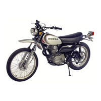
Honda CL250 Shop Manual (220 pages)
Brand:
Honda
| Category:
Motorcycle
| Size: 21.78 MB
Table of Contents
Features
4
Frame
5
Contents
6
Technical Data
12
CB250 Driving Performance Curve
14
CB250 Engine Performance Curve
14
CL250 Driving Performance Curve
15
CL250 Engine Performance Curve
15
CB350 Driving Performance Curve
16
CB350 Engine Performance Curve
16
CL350 Driving Performance Curve
17
CL350 Engine Performance Curve
17
CB250/350 Dimensional Drawing
18
CL250/350 Dimensional Drawing
19
Special Tools
20
Engine
22
Sectional View of Engine
22
Engine Construction
24
Power Transmission
24
Lubrication
25
Oil Lubricating System
25
Dismounting the Engine
26
Remounting the Engine
27
Cam Case and Cylinder Head
28
Engine Disassembly
29
Inspection
30
Engine Reassembly
31
Camshaft Construction
32
Rocker Arm and Rocker Arm Pin
33
Rocker Arm and Rocker Arm Pin Disassembly
33
Rocker Arm and Rocker Arm Pin Reassembly
33
Valve and Valve Spring Construction
34
Valve and Valve Spring Disassembly
34
Valve and Valve Spring Reassembly
36
Sectional View of Valve Seat
36
Valve Seat Cutter
36
Suction Cup Lapping Tool
36
Cylinder Construction
37
Cylinder Disassembly
37
Cylinder Inspection
37
Cylinder Reassembly
38
Piston Description
38
Piston Ring Construction
39
Piston and Piston Ring Disassembly
40
Piston and Piston Ring Inspection
40
Dimension of Piston
41
Measuring the Piston Diameter
41
Piston Groove and Piston Ring Clearance
41
Piston Pin Diameter
42
Piston Ring and Gap
42
Ring Tension
42
Ring Width and Thickness
42
Piston and Piston Pin Reassembly
43
Rolling the Piston Ring in the Piston Groove
43
Manufacturer's Mark
43
Setting the Piston Pin Clip
43
Sectional View of Cam Chain
44
Cam Chain Tensioner and Guide Roller Construction
45
Tensioner and Guide Roller Disassembly
45
Crankcase Cover (Right) Construction
46
Crankcase Cover (Right) Disassembly
46
Tensioner and Guide Roller Reassembly
46
Crankcase Cover (Right) Reassembly
47
Oil Filter Construction
47
Oil Filter Reassembly
48
Clutch Construction
49
Sectional View of Clutch
50
Clutch Adjusting Mechanism
50
Oil Pump Construction
51
Clutch Disassembly
51
Clutch Inspection
52
Clutch Reassembly
52
Crankcase Cover (Left) Construction
53
Crankcase Cover (Left) Disassembly
53
Crankcase Cover (Left) Reassembly
53
Upper and Lower Crankcase Construction
54
Upper and Lower Crankcase Disassembly
54
Oil Separator Operation
54
Upper and Lower Crankcase Inspection
55
Upper and Lower Crankcase Reassembly
55
Crankshaft Construction
55
Crankshaft Balance
56
Connecting Rod Construction
57
Crankshaft Disassembly
57
Crankshaft Inspection
58
Crankshaft Runout Measuring
58
Measuring the Diametrical Clearance
58
Crankshaft Reassembly
59
Measuring the Connecting Rod Diametrical Clearance
59
Measuring the Connecting Side Clearance
59
Tightening the Bearing Cap Bolts
59
Kick Starter Construction
60
Kick Starter Disassembly
60
Kick Starter Inspection
60
Kick Starter Reassembly
60
Transmission
61
Transmission Disassembly
62
Transmission Inspection
62
Transmission Reassembly
63
Gear Shift Construction
63
Measuring the Gear Backlash
63
Assembling the Gears
63
Gear Shift Disassembly
64
Gear Shift Mechanism
64
Removing the Gear Shift Drum
64
Gear Shift Inspection
65
Gear Shift Reassembly
65
Measuring the Flatness of Gear Shift Fork
65
Measuring the Outer Diameter
65
Carburetor
66
Air Flow
66
Fuel Flow
66
Operation and Adjustment
67
Float System
67
Choke
67
Sectional View of Carburetor
67
High Speed System
69
Maximum Speed System
69
Carburetor Setting Table
70
Handlebar Construction
72
Handle Disassembly
72
External View of Handlebar
72
Removing Brake Cable
72
Handlebar Inspection
73
Removing the Handlebar
73
Removing the Throttle Cable
73
Fork Top Bridge Construction
74
Throttle Cable Play Adjustment
74
Adjusting the Front Brake
74
Joint the Electrical Leads
74
Removing the Fork Top Bridge
75
Component Parts of Fork Top Bridge
75
Top Bridge Holder Installing 8Mm Nut
75
Front Cushion Construction
76
Front Fork Assembly
76
Cross-Section of Front Cushion (CL250/350)
76
Cross-Section of Front Cushion (CB250/350)
77
Front Cushion Operation
77
Front Cushion Disassembly
78
Removing the Front Fender
78
Removing the Front Fork Assembly
78
Removing 44Mm Circlip
78
Front Cushion Inspection
79
Front Cushion Reassembly
79
Front Cushion Spring Measurement
79
Component Parts of Front Fork Pipe
79
Driving Oil Seal
80
Installing the Front Fork into the Steering
80
Steering Stem Construction
81
Steering Stem Disassembly
81
Steering Stem Inspection
81
Sectional View of Steering Stem
81
Steering Stem Reassembly
82
Fuel Tank Construction
82
Schematic View of Tank Rubber Cushion
82
Fuel Tank Disassembly
83
Fuel Tank Inspection
83
Fuel Tank Reassembly
83
Component Parts of Fuel Strainer
83
Frame Body Construction
84
Schematic View of Frame Body
84
Frame Body Disassembly
85
Frame Body Inspection
85
Frame Body Reassembly
85
Seat Construction
86
Seat Disassembly
86
Seat Inspection
86
Seat Reassembly
86
Stand, Brake Pedal and Step Bar Construction
87
Stand, Brake Pedal and Step Bar Disassembly
87
Exploded View of Stand and Brake Pedal
87
Stand, Brake Pedal and Step Bar Inspection
88
Stand, Brake Pedal and Step Bar Reassembly
88
Removing the Step Bar
88
Fixing the Main Stand with 6Mm Bolts
88
Muffler
89
Air Cleaner
89
Installing the Exhaust Pipe
89
Cross-Section of Exhaust Pipe and Nut
89
Air Flow in Dual Type Air Cleaner
90
Removing the Air Cleaner Case
90
Rear Fork and Rear Fender Construction
91
Exploded View Rear Fork and Rear Fender
91
Rear Fork and Rear Fender Disassembly
92
Rear Fork and Rear Fender Inspection
92
Twist Measurement of Rear Fork
92
Removing the Rear Fork
92
Rear Cushion Construction
93
Sectional View of Rear Cushion
93
Cross-Section of the Rear Fork Pivot Portion
93
Feature and Performance
94
Rear Cushion Adjustment
94
Removing the Rear Cushion Assembly
95
Disassembling Rear Cushion
95
Component Parts of Rear Cushion
95
Assembling Rear Cushion
95
Check of Cushion
96
Mounting Bolts and Nuts of Rear Cushion
96
Front Wheel Construction
97
Front Wheel Disassembly
97
Removing the Brake Stopper Arm
97
Removing the Front Wheel Axle
98
Removing the Oil Seal
98
Removing the Front Brake Shoe
98
Front Wheel Reassembly
99
Checking the Front Wheel Rim for Runout
99
Checking the Front Axle for Bend
99
Installing the Tire
99
Tapping Around the Tire
100
Driving the Bearing
100
Installing the Brake Arm
100
Valve Angle
100
Rear Wheel Construction
101
Cross-Section of Rear Wheel
101
Rear Wheel Disassembly
102
Removing the Drive Chain Joint
102
Removing the Final Driven Sprocket
102
Removing the Bearing Retainer
102
Removing the Rear Brake Shoe
103
Removing the Rear Wheel Tire
103
Checking the Front Wheel Rin for Runout
103
Checking the Rear Axle for Bend
103
Measuring the Outside of the Rear Brake Shoe
104
Inspection the Inside of Tire
104
Rear Wheel Reassembly
105
Installing the Bearing
105
Assembling the Final Driven Sprocket
105
Installing the Brake Shoe
105
Setting the Chain Clip
106
Rear Brake Pedal Play
106
Adjusting the Rear Brake
106
Adjusting Slack of Drive Chain
106
Electrical Parts
108
Electrical Equipment
108
Power Supply System
108
Ignition Circuit
108
Sectional View of Ignition Coil
109
Ignition System View
109
Spark Characteristics
109
Vertical Type Electrode Space
109
Spark Advancer
110
60 Degree Type Electrode Space
110
Contact Breaker
111
Spark Advancer Mechanism
111
Spark Advancer Characteristics
111
Condenser
112
Spark Plug
113
Cross-Section of Spark Plug
114
Electrode Construction
115
Insulator Construction
115
Spark Plug Thermal Characteristics
116
Spark Plug Reach
117
Heat Dissipation
117
Comparison of Hear Characteristics
117
Noise Suppressor
118
Power Circuit
119
A.C. Generator
119
Current Limiter
119
Pointless Regulator
120
Pointless Regulator Characteristics
120
A.C. Generator Capacity for the Honda 250/350
121
Pointless Regulator Circuit Diagram
121
A.C. Generator Battery Changing Characteristics
121
Selenium Rectifier
122
Selenium Rectifier Stuck
122
Construction of Selenium Rectifier
122
Selenium Symbol
122
Battery
124
Battery Construction
124
Battery Charging Procedure
125
Measuring the Specific Gravity
125
Specific Gravity and Residual Capacity Chart
125
Series Connection for Multiple Charging
126
Preventative Maintenance
127
Vacuum Sealed Dry Charged Battery
128
Comparison of Performances
128
Care During Storage
129
Instruction before Use
129
Aluminum Foil Packing Tight on the Battery
129
Aluminum Foil Packing Loose on the Battery
129
Electric Starter
130
Starting Circuit
130
Starting Motor
130
Starting Motor Characteristics
131
Starter Reduction
131
Starter Circuit Diagram
131
Starting Motor Reduction Gear Components
131
Electric Starter Removal
132
Electric Starter Servicing
132
Starting Clutch
133
Sectional View of Commutator
133
Commutator Correction
133
Starter Solenoid Switch
135
Starter Solenoid Switch with the Cover Opened
135
Safety Devices
136
Horn
136
Horn Construction
137
Horn Servicing
138
Tail-Stoplight
138
Cross-Section of Tail/Stop Light
138
Pilot Lamp
139
Speedometer/Tachometer
139
Characteristics of the Speedometer/Tachometer
140
Headlight
141
Headlight Construction
141
Flasher Relay Operation
142
Combination Switch Closed
142
Flasher Switch (WS) Closed (Lights On)
142
Point (P) Open (Light Off)
142
Switches
143
Combination Switch
143
Point(P) Closed (Light On)
143
Signal-Stat Flasher Relay
143
Stoplight Switch
144
Starter/Lighting Switch
144
Winker-Horn Switch
144
Neutral Switch
144
Wire Harness
145
Service Tester
146
Meter Reading
146
Meter Scale Panel
146
Usage by Item
147
Selector Switch
147
Test Lead Wire Connection
147
Continuity Test of the Combination Switch
147
Rectifier Resistance Measurement
148
Condenser Insulation Test
148
Rectifier Wiring Diagram
148
Short-Circuiting of the Condenser
149
Condenser Capacity Measuring
149
D.C. Voltage Measurement
150
D.C. Current Measurement
150
Engine Revolution Measurement
151
Timing Measurement
151
Connection of the Timing Light Cord
151
Coil Test Connection
152
Coil Test (Negative Sparking)
152
Coil Test (Positive Sparking)
152
Starting Motor Current Measurement
153
Battery Trouble Shooting and Corrective Action
154
Inspection and Adjustment
156
Preventive Maintenance
156
Engine Tune-Up
156
Compression Measurement
156
Valve-Tappet Clearance Adjustment
157
Rated Compression
157
Aligning the 'LT' Mark
157
Adjusting Tappet Clearance
158
Rocker Arm Pin Turning Direction
158
Ignition Timing Adjustment
159
Point Surface Correction
159
Aligning the 'LF' Mark
160
Start of Spark Advancing
160
End of Spark Advancing
160
Spark Plugs
161
Spark Gap Measuring
161
Spark Plug Clearing
161
Fuel System
162
Cleaning Oil Filter
162
Filler Cap Cross-Section Showing Breather Path
162
Gasoline Flow through the Fuel Cock
162
Air Cleaner Element Cleaning
163
Air Cleaner Case Removing
163
Oil Filter Cover Installation
163
Rotor Cap Installation
163
Clutch Adjustment
164
Clutch Lever Play
164
Sectional View of Air Flow
164
Air Cleaner Cleaning
164
Carburetor Cleaning and Adjustment
165
Idling Adjustment
166
Cross-Section of Carburetor
166
Throttle Valve Adjustment
167
Oil Filter Cap
167
Oil Drain Plug
167
Grease
168
Drive Chain Adjustment
169
Front Fork Oil Change
169
Drive Chain Slackness and Adjustment
169
Front Fork Bolt
169
Brake Adjustment
170
Front Brake Lever Play
170
Battery Inspection
171
Rear Brake Adjustment
171
Seat Latch
171
Checking Parts for Tightness
172
Spokes
173
Retightening Spoke
173
Left Side
173
Right Side
173
Periodic Inspection and Maintenance
174
Trouble Shooting
175
Engine Does Not Start of Hard Starting
175
Loss of Speed and Drop in Power
176
Improper RPM
178
Excessive Oil Consumption
181
Clutch Operates Faulty
182
Shift Operates Faulty
182
Engine Runs with Unusual Noise
183
Vehicle Steers Faulty
183
Front or Rear Suspension Functions Faulty
184
Defective Brake
184
Quick Expansion of Drive Chain
185
Wiring Diagram(General Type)
186
Wiring Diagram (U.S.A. Type)
187
Wiring Diagram (U.K. Type)
188
Wiring Diagram (Germany Type)
189
Advertisement
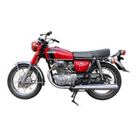
Honda CL250 Shop Manual (180 pages)
Honda Motorcycle CB250/350, CL250/350, SL350
Brand:
Honda
| Category:
Motorcycle
| Size: 36.12 MB
Table of Contents
Contents
5
Technical Data
14
Special Tools
28
Minor Model Change Table of Principal Modifications
32
Engine
42
Main Features
42
Power Transmission System
42
Dismounting the Engine
42
Remounting the Engine
43
Valve Mechanism
44
Description
44
Disassembly
44
Inspection
46
Compression Pressure
46
Adjusting the Engine to the Proper Compression Pressure
46
Valve Tappet Clearance Inspection and Adjustment
46
Camshaft Side Clearance
47
Cam Diameter
47
Camshaft Mounting End
48
Rocker Arm Pin Diameter
48
Deformation of the Gasketing Surface
48
Carbon Removal
48
Valve Seat Contact
49
Valve Stem Clearance
50
Valve Stem Diameter
50
Valve Guide Replacement
50
Valve Spring Dimension
50
Reassembly
51
Valve Timing
51
Pistons and Cylinders
52
Cylinder Boring and Honing
53
Piston Dimension
53
Piston Ring Side Clearance
53
Piston Ring End Gap
54
Piston Ring Thickness
54
Piston Pin Bore
54
Piston Pin Diameter
54
Cam Chain Tensioner (Hydraulic Type) Description
55
Cam Chain Tensioner (Hydraulic Type) Disassembly
56
Cam Chain Tensioner Inspection
56
Cam Chain Tensioner Reassembly
56
Lubricating System Description
57
Lubricating System Disassembly
58
Lubricating System Inspection
59
Engine Oil Check and Change
59
Cleaning Air Filter
59
R. Crankcase and Oil Filter Inspection
60
Oil Pump Body Bore Dimension
60
Oil Pump Plunger Dimension
60
Lubricating System Reassembly
61
Clutch Description
61
Clutch Disassembly
62
Clutch Inspection
62
Clutch Reassembly
63
Friction Disc Dimension
63
Clutch Plate Warpage
63
Clutch Spring Dimension
63
Crankshaft and Connecting Rods Description
64
Crankshaft and Connecting Rods Disassembly
64
Crankshaft and Connecting Rods Inspection
65
Measure Amount of Bend
65
Main Bearing Diametrical Clearance
65
Connecting Rod Diametrical Clearance
65
Crankshaft and Connecting Rods Reassembly
66
Transmission Description
66
Transmission Disassembly
66
Connecting Rod Small End Bore
66
Transmission Inspection
67
Measuring Backlash
67
Wear to Transmission Gear
67
Clearance between Gear and Sahft
67
Transmission Reassembly
68
Gear Shift Mechanism Description
68
Gear Shift Mechanism Disassembly
69
Gear Shift Mechanism Inspection
69
Gear Shift Mechanism Reassembly
70
Kick Starter Description
70
Kick Starter Disassembly
70
Kick Starter Reassembly
70
Crankcases Description
71
Oil Separator Operation
71
Crankcases Disassembly
71
Crankcases Inspection
71
Crankcases Reassembly
72
Carburetor Description
72
Sectional View of Carburetor
72
Carburetor Disassembly
73
Carburetor Inspection
73
Idling Adjustment
73
Synchronizing the Throttle Valve
73
Frame
74
Handlebar Description
74
Handlebar Disassembly
74
Handlebar Inspection
75
Handlebar Reassembly
75
Fork Top Bridge Description
76
Fork Top Bridge Disassembly
76
Fork Top Bridge Inspection
76
Fork Top Bridge Reassembly
76
Front Cushion (Piston Type) Description
77
Front Fork Assembly
77
Front Cushion Description
78
Front Fork Unit
78
Front Cushion Operation
79
Front Cushion Disassembly (Piston Type)
79
Front Cushion Inspection (Piston Type)
80
Front Fork Oil Change
80
Inspect for Oil Leak
80
Inspect Front Cushion Spring
80
Front Cushion Reassembly
81
Front Fork Piston Diameter
81
Front Fork Bottom Case Diameter
81
Front Cushion Description (Rod Type)
82
Front Cushion Disassembly
82
Front Cushion Inspection
83
Steering Stem Description
84
Steering Stem Disassembly
84
Steering Stem Inspection
84
Steering Stem Reassembly
84
Fuel Tank Description
85
Fuel Tank Disassembly
85
Fuel Tank Inspection
86
Fuel Tank Reassembly
86
Frame Body Description
86
Frame Body Disassembly
87
Frame Body Inspection
87
Frame Body Reassembly
87
Seat Description
87
Seat Disassembly
88
Seat Inspection
88
Seat Reassembly
88
Stands and Brake Pedal Description
88
Stands and Brake Pedal Inspection
89
Stands and Brake Pedal Reassembly
89
Exhaust Pipes and Mufflers Description
89
Exhaust Pipes and Mufflers Disassembly
90
Exhaust Pipes and Mufflers Inspection
90
Exhaust Pipes and Mufflers Reassembly
90
Air Cleaner Description
90
Rear Fork and Rear Fender Description
91
Rear Fork and Rear Fender Disassembly
91
Rear Fork and Rear Fender Inspection
92
Rear Fork and Rear Fender Reassembly
92
Rear Cushion Description
93
Rear Cushion Operation
93
Rear Suspension Adjustment
93
Rear Cushion Disassembly
95
Rear Cushion Inspection
95
Rear Cushion Reassembly
96
Front Wheel Description
96
Front Wheel Disassembly
97
Front Wheel Inspection
97
Front Wheel Reassembly
98
Front Axle Bend
98
Radial Clearance of 6302R Ball Bearing
98
Thickness of Brake Lining
98
Front Wheel Disassembled
100
To Serve Front Wheel
100
Front Wheel Torque Specifications
100
Front Wheel Assembly
102
Disassembly of Calipers and Master Cylinder
104
Master Cylinder Disassembled
106
Inspection of Calipers and Master Cylinder
106
Assembly of Calipers and Master Cylinder
107
Measure the Caliper Cylinder and Piston
107
Measure the Master Cylinder and Piston
107
Adjustment of Disc Brake
108
Check the Brake Fluid Level
108
Bleed the Brake Lines
109
Rear Wheel Description
109
Rear Wheel Disassembly
110
Rear Wheel Inspection
111
Rear Axle Bend
111
Rear Brake Drum Inside Diameter
111
Rear Wheel Reassembly
112
Electrical Parts
114
Ignition System
114
Ignition Coil Description
114
Ignition Coil Removal
114
Ignition Coil Reassembly
115
Ignition Coil Inspection
115
Ignition Coil Inspection with a Service Tester
115
Breaker Point Description
116
Breaker Point Disassembly
116
Breaker Point Inspection
116
Breaker Point Reassembly
118
Condenser Description
118
Condenser Removal
118
Condenser Inspection
118
Spark Plug Description
119
Spark Plug Removal
120
Spark Plug Inspection
120
Spark Plug Installation
120
Noise Suppressor Description
121
Noise Suppressor Removal
121
Noise Suppressor Inspection
121
Noise Suppressor Reinstallation
121
A.C. Generator Performance Characteristics
122
Silicon Current Regular Description
122
Silicon Current Regular Disassembly
122
Silicon Current Regular Inspection
123
Silicon Current Regular Reassembly
123
Rectifying System Description
123
Rectifying System Disassembly
123
Rectifying System Reassembly
124
Battery Description
124
Battery Removal
125
Battery Inspection
125
Battery Charging Procedure
125
Battery Charging
126
Quick Charger
126
Battery Trouble Shooting and Corrective Action
128
Starting System
128
Starting Motor Description
128
Starting Motor Disassembly
129
Starting Motor Inspection
129
Armature Insulation Test
129
Measure the Starting Current
129
Starting Motor Specification
130
Starting Motor Reassembly
130
Starting Clutch Description
130
Starting Clutch Inspection
130
Starting Clutch Reassembly
131
Starter Magnetic Switch Description
131
Starter Magnetic Switch Removal
131
Starter Magnetic Switch Inspection
131
Safety Equipment
132
Horn Description
132
Horn Removal
132
Horn Inspection
132
Headlight Description
133
Headlight Removal
133
Headlight Inspection
133
Headlight Reassembly
134
Tail/Stop Light Removal
134
Tail/Stop Light Inspection
134
Tail/Stop Light Reassembly
134
Winker Relay Description
135
Winker Relay Removal
135
Winker Relay Inspection
135
Winker Relay Reassembly
135
Switches
136
Ignition Switch Removal
136
Stoplight Switch Removal
136
Stoplight Switch Inspetion
136
Starter Switch Button and Lighting Switch Removal
137
Starter Switch Button and Lighting Switch Reassembly
137
Starter Switch Button and Lighting Switch Inspection
137
Turn Signal and Horn Control Switch Disassembly
137
Neutral Switch Inspection
138
Neutral Switch Removal
138
Neutral Switch Reassembly
138
Wiring Diagram
138
Wiring Harness Description
139
Wiring Harness Removal
139
Wiring Harness Inspection
139
Wiring Harness Reassembly
139
Engine (SL350)
140
General Description of the SL350
140
Dismounting the Engine (SL350)
140
Remounting the Engine (SL350)
140
Primary Kick Starter
141
Carburetor Specifications (SL350)
142
Carburetor Circuits
142
Main Circuit
143
Float Circuit
143
Idle Speed Adjustment (SL350)
144
Float Level Adjustment (SL350)
144
Frame (SL350)
145
CB250K4 Wiring Diagram
156
CB350K4 Wiring Diagram
157
CB350K4 Wiring Diagram (General Type)
158
CL350K4 Wiring Diagram
159
CL350K4 Wiring Diagram (General Type)
160
SL350K2 Wiring Diagram
161
CB350G Wiring Diagram
162
Maintenance Schedule
164
Tightening Torque Standard
165
Trouble Shooting
166
Engine Does Not Start or Hard Starting
166
Loss of Speed and Drop in Power
167
Improper Running of Engine (Particularly at Low Speed and Idling)
169
Improper Running of Engine (High Speed)
170
Excessive Oil Consumption
172
Exhaust Smoke
172
Clutch Operates Faulty
173
Shift Operates Faulty
173
Engine Runs with Unusual Noise
174
Vehicle Steers Faulty
174
Advertisement
Related Products
Honda CL250K2
Honda CL200
Honda CL350
Honda CL350K2
Honda CL350K3
Honda CL100
Honda CLICK150i 2019
Honda CLICK150i EN 2020
Honda CL500A 2023
Honda CL500A 2022
Honda Categories
Motorcycle
Automobile
Lawn Mower
Offroad Vehicle
Engine
More Honda Manuals
Login
Sign In
OR
Sign in with Facebook
Sign in with Google
Upload manual
Upload from disk
Upload from URL