Sign In
Upload
Manuals
Brands
Honda Manuals
Motorcycle
1978 CB400T
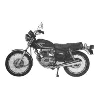
Honda 1978 CB400T Motorcycle Manuals
Manuals and User Guides for Honda 1978 CB400T Motorcycle. We have
1
Honda 1978 CB400T Motorcycle manual available for free PDF download: Shop Manual
Honda 1978 CB400T Shop Manual (318 pages)
Brand:
Honda
| Category:
Motorcycle
| Size: 29.89 MB
Table of Contents
Introduction
2
How to Use this Manual
2
Table of Contents
2
Model Identification
3
Identification Number
3
General Information Contents
4
General Safety
4
Service Rules
4
Specifications
5
Torque Value
7
Standard Torque Specifications
8
Special Tools
9
Common Tools
9
Wiring Diagrams CB400T Type I
10
CB400T Type II
11
Cable and Hardness Routing
12
Maintenance Schedule
15
Lubrication Diagram
17
Lubrication Contents
18
Service Information
18
Troubleshooting
18
Engie Oil and Filter Change
19
Engine Oil Level
19
Swingarm Pivot
20
Drive Chain
20
Miscellaneous Lube Points
21
Inspection and Adjustment Contents
22
Spark Plugs
23
Ignition Timing Check
23
Engine
23
Valve Clearance Adjustment
24
Cam Chain Adjustment
24
Idle Speed Adjustment
25
Throttle Operation
25
Carburetor Synchronization
26
Choke Mechanism Maintenance
27
Fast Idle Adjustment
27
Adjustment
27
Balancer Chain Adjustment
28
Air Cleaner Maintenance
28
Fuel Line Inspection
29
Compression Test
29
Clutch Adjustment
30
Brake Fluid Inspection
31
Chassis
31
Front Brake Drum
31
Front Brake Disc
31
Rear Brake
32
Brake Pedal Height
32
Brake Pedal Free Play
33
Stoplight Switch
33
Brake Shoe Inspection (Wear Indicator)
33
Side Stand
34
Wheel Spoke Retightening
35
Wheels/Spokes
35
Tire Pressure
35
Battery Electrolyte
35
Fuel System
37
Fuel System Contents
38
Carburetor Removal
39
Carburetor Separation
39
Vacuum Cylinder Disassembly
41
Float Chamber Disassembly
42
Air Cutoff Valve Disassembly
43
Craburetor Assembly
44
Float Level Adjustment
44
Component Assembly
44
Craburetor Installation
45
Fuel Tank
46
Air Cleaner Case Removal/Installation
46
Crankcase Ventilation System
46
Engine Removal and Installation
48
Cylinder Head/Valve
53
Rocker Arm and Camshaft Removal
54
Rocker Arm Inspection
55
Cam Bearing Surface Inspection
56
Camshaft Holder Rocker Arm Shaft Hole Inspection
56
Rocker Arm Shaft Inspection
56
Camshaft Oil Clearance
57
Cylinder Head Removal
58
Camshaft Runout
58
Cam Lobe Inspection
58
Cylinder Head Disassembly
59
Cylinder Head Inspection
60
Valve Spring Free Length Inspection
60
Valve Stem-To-Guide Clearance
61
Valve Guide Replacement
62
Valve Seat Inspection and Grinding
63
Cylinder Head Assembly
64
Rocker Arm Assembly
65
Cylinder Head Installation
65
Camshaft/Rocker Arm Installation
66
Cylinder/Piston
71
Cylinder/Piston Contents
72
Cylinder Removal
73
Cylinder Inspection
73
Piston Removal
74
Piston/Piston Ring Inspection
74
Piston Ring Installation
76
Cylinder Installation
78
Piston Installation
78
Clutch/Oil Pump
81
Clutch/Oil Pump Contents
82
R-Crankcase Cover Removal
84
Clutch
84
Clutch Lifter Removal
84
Clutch Lifter Plate Removal
84
Clutch Removal
85
Clatch Center, Plate and Disc Removal
85
Clutch Disc Inspection
86
Disc Spring Inspection
86
Clutch Spring Inspection
86
Plate Inspection
87
Clutch Outer and Outer Guide Inspection
87
Clutch Installation
87
Clutch Lifter and Right Crankcase Cover Installation
90
Oil Pump
92
Oil Pump Removal
92
Oil Pump Disassembly
92
Oil Pump Inspection
93
Oil Pump Assembly
94
Oil Pump Installation
94
Oil Pressure Relief Valve
95
Right-Crankcase Cover Installation
96
Crankcase
97
Crankcase Contents
98
Crankcase Removal of Parts
99
A.C. Generator Removal
99
Crankcase Disassembly
100
Crankcase Assembly
100
Installation of Parts
102
A.C. Generator Installation
102
Crankshaft/Balancer
103
Crankshaft/Balancer Contents
104
Balancer Removal
106
Balancer Inspection
108
Connecting Rod Removal
109
Crankshaft/Starter Clutch Removal
110
Starter Clutch Inspection
110
Starter Drive Gear Inspection
110
Crankshaft Inspection
110
Electric Starter Idle Gear Removal
111
Electric Starter Idle Gear Inspection
111
Bearing Inspection
112
Connecting Rods
112
Main Bearings
113
Bearing Selection
114
Connecting Rod Bearing Inserts
114
Main Bearing
115
Starter Idle Gear Installation
116
Starter Clutch/Crankshaft Installation
116
Connecting Rod Intsallation
117
Balancer Installation
118
Transmission
123
Table of Contents
124
Transmission Contents
124
Troubleshooting
125
Gearshift Linkage Disassembly
126
Transmission Disassembly
126
Gear Dog Minimum Clearance at End
127
Transmission Inspection
128
Gearshift Drum/Shift Fork Removal
129
Gearshift Drum and Shift Fork Inspection
129
Kick Starter Inspecction
131
Kick Starter Disassembly
131
Kick Starter Assembly
132
Gearshift Drum/Shift Fork Installation
133
Transmission Assembly
134
Gearshift Linkage Assembly
136
Front Wheel/Brake/Suspension
137
Front Wheel/Brake/Suspension Contents
138
Troubleshooting
139
Headlight
140
Headlight Case Removal
140
Headlight Installation
140
Wiring Connection in Headlight Case
140
Cluster Disassembly
141
Indicator Lamp/Combination Switch Replacement
141
Instruments
141
Meter Lamp/Meter Replacement
141
Handlebar
142
Handlebar Installation
142
Handlebar Removal
142
Front Wheel Removal/ Disassembly/Assembly
143
Axle Inspection
144
Wheel Bearing Inspection
144
Wheel Inspection
144
Wheel Disassembly
145
Front Wheel Assembly
146
Brake Rod Adjustment
147
Brake Shoe Replacement
147
Front Brake Lining Thickness
147
Front Brake Panel
147
Front Wheel Installation
148
Front Fork
149
Front Fork Removal
149
Front Damper Spring Free Length Inspection
150
Front Fork Disassembly
150
Fork Tube/Fork Slide/Piston Inspection
151
Oil Seal Removal
151
Front Fork Assembly
152
Filling with Fork Oil
153
Oil Seal Installation
153
Front Fork Installation
154
Fork Top Bridge Removal
155
Steering Stem
155
Steering Head Adjuster Removal
156
Steering Lock Removal/Installation
156
Steering Head Adjuster Installation
157
Top Bridge Installation
157
Rear Wheel/Brake/Suspension
159
Rear Wheel/Brake/Suspension Contents
160
Service Information
160
Troubleshooting
161
Axle Shaft Bend Inspection
162
Rear Wheel Bearing Play Inspection
162
Rear Wheel Removal/Disassembly/Assembly
162
Rear Wheel Rim Runout Inspection
162
Damper Rubber Inspection
164
Final Driven Sprocket
164
Final Driven Sprocket Inspection
164
Rear Wheel Hub Inspection
164
Brake Drum I.D. Inspection
165
Rear Brake Lining Thickness
165
Rear Brake Panel
165
Rear Brake Shoe Replacement
165
Rear Wheel Installation
166
Shock Absorber
167
Shock Absorber Disassembly
167
Shock Absorber Removal
167
IIV
168
Shock Absorber Assembly
168
Shock Absorber Installation
168
Shock Absorber Spring
168
Swing Arm Removal
169
Swingarm Disassembly/Assembly
169
Swingarm Installation
169
Brake Pedal Removal/Installation
170
Rear Brake Pedal
170
Rear Brake Pedal Height
170
Hydraulic Disc Brake
171
Hydraulic Disc Brake Contents
172
Air Bleeding
173
Brake Fluid Draining
173
Brake Fluid Filling
173
Brake Fluid Replacement/Air Bleeding
173
Brake Pad Replacement
174
Brake Pad Wear Check
174
Brake Pads/Disc Plate
174
Brake Disc Warpage
176
Disc Thickness
176
Brake Master Cylinder
177
Master Cylinder I.D. Inspection
177
Matser Cylinder Disassembly
177
Master Cylinder Assembly
178
Matser Piston O.D. Ispection
178
Brake Caliper
179
Brake Caliper Disassembly
179
Caliper a Removal
179
Caliper Assembly
179
Caliper Carrier/Carrier Assembly
180
Caliper Carrier/Carrier Disassembly
180
Caliper Cylinder I.D.
180
Caliper Piston O.D.
180
Caliper Installation
181
Battery/Charge System Contents
182
Battery Removal
184
Testing Specific Gravity
184
Battery Charging
185
Charging Output Test
185
Charging System
185
Stator Coil Continuity Test
186
Voltage Regulator/Rectifier Test
186
A.C. Generator Removal/Installation
187
Voltage Regulator Performance Test
187
Ignition System Contents
188
Ignition Coil Performance Test
190
Ignition Coil Removal
190
Schematic Diagram Od C.D.I. System
190
Spark Plug
190
C.D.I. Unit
191
A.C. Generator Inspection
193
Starter Motor Contents
194
Brush Inspection
195
Commutator Inspection
195
Starter Motor Removal
195
Field Coil Inspection
196
Magnetic Switch Inspection
197
Starter Clutch
197
Balancer Mechanism
198
Front Balancer Shaft
198
Rubber Dampers
198
Technical Features
198
Operating Principle of Balancer
199
3 Valve, Short Stroke Engine
201
C.D.I. System
202
Features
202
Operating Principle
203
Advancer Operation
204
Engine Does Not Start or Is Hard to Start
206
Engine Lacks Power
207
Poor Performance at Low and Idle Speeds
209
Poor Handling
210
Poor Performance at High Speed
210
'79 Addendum Table of Contents
214
A L L Information, Illustrations, Direc
214
Duced Without Written Permission
214
MAKE CHANGES at any Tlme WITHOUT
214
Motor Co., Lto Reserves the Right to
214
NO PART of Thls PUBLICATION MAY be REPRO
214
Notice and Without Incurring any
214
Obligation Whatever
214
PRODUCT INFORMATION AVAILABLE a T the Tlme of APPROVAL for PRINTING. HONDA
214
TIONS and SPECIFICATIONS INCLUDED I N Thls
214
Maintenance Schedule CB400T
215
Inspection and Adjustment Balancer Chain Tension
216
Brake Fluid
220
Brake Fluid Replacement
220
Brake System Draining
220
Fluid Level
220
Brake Master Cylinder Disassembly
221
I.D. Inspection
221
Master Piston O.D. Inspection
222
Model Identification
225
Specifications
226
Ill. TORQUE VALUES
229
Wiring Diagrams CM400T
232
Wiring Diagrams CM400A
233
Cable and Harness Routing CM400T
234
Cable and Harness Routing CM400A
236
Emission Control Label
238
Maintenance Schedule CM400T
239
Maintenance Schedule CM400A
240
Air Cleaner
241
Inspection and Adjustment
241
Hydraulic Disc Brake
242
Fuel System
243
High Altitude Adjustment
243
'80 Adendum Contents
244
Maintenance Schedule CM400T
249
Control Cable Lubrication
251
Engine Oil Recommendation
251
Oil Viscosity
251
Recommended Spark Plug
251
Carburetor Assembly
252
Carburetor Specifications
252
Float Level Inspection
252
Accelerator Pump Adjustment
253
Accelerator Pump Inspection
253
Pilot Screw Adjustment Idle Drop Procedure
254
Pilot Screw Removal/Installation
254
Wiring Diagram CM400T
256
Wiring Diagram CM400A
257
'80 CB400T Addendum Contents
258
Inspection and Adjustment
258
Specifications
258
Cable Routing
262
Spark Plug Replacement
265
High Altitude Carburetor Specifications
269
Limiter Cap Installation
269
Cylinder Head/Valves
270
Oil Pressure Relief Valve Removal
270
Wiring Diagram '80 CB400T Addendum
272
'80 CM400E Addendum Contents
274
Maintenance Schedule CM400E
278
Cable and Harness Routing
279
Battery
283
Wheel Spoke Tightening
283
Wiring Diagram CM400E
284
'81 CB/CM400'S Addendum Contents
286
CB400T, CM400C: Front Disc Brake Pad
297
Front Air Forks
297
Recommended Tire Pressures and Sizes
298
Wheels
298
Front Air Forks Removal
299
Front Air Forks Disassembly
300
Bushing/Back-Up Ring Inspection
302
Fork Tube/Piston Inspection
302
Spring Inspection
302
Assembly
303
Installation
305
CB400T/CM400C: Hydraulic Disc Brake
307
Cb400Tlcm400C
307
Caliper Removal
308
Caliper Disassembly
309
Caliper Carrier Assembly
311
Caliper Carrier Disassembly
311
Cable and Harness Routing
313
Wiring Diagram CM400T/C
316
Advertisement
Advertisement
Related Products
Honda 1978 CB400A
Honda 1979 Elsinore CR250R
Honda 1978 XL250S
Honda 1979 CBX
Honda 1973 SL-125
Honda 1976 TL125
Honda 1979 CB400T
Honda 1979 CM400T
Honda 1969 ST 70 DII
Honda 1981 CM400A
Honda Categories
Motorcycle
Automobile
Lawn Mower
Offroad Vehicle
Engine
More Honda Manuals
Login
Sign In
OR
Sign in with Facebook
Sign in with Google
Upload manual
Upload from disk
Upload from URL