Sign In
Upload
Manuals
Brands
Hitachi Manuals
Industrial PC
HF-W7500 40
Hitachi HF-W7500 40 Manuals
Manuals and User Guides for Hitachi HF-W7500 40. We have
1
Hitachi HF-W7500 40 manual available for free PDF download: Manual
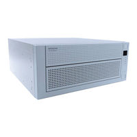
Hitachi HF-W7500 40 Manual (161 pages)
Industrial Computer, RAS Features
Brand:
Hitachi
| Category:
Industrial PC
| Size: 1.09 MB
Table of Contents
Table of Contents
12
Chapter 1 Capabilities of the Ras Feature
18
Table 1-1 Overview of the RAS Feature
18
Figure 1-1 RAS Setup Window
19
Figure 1-2 Hardware Status Icon
20
Chapter 2 Items Monitored by the Ras Feature
24
Fan Monitoring
24
Table 2-1 State of the Equipment in Terms of Fan Monitoring and State of the MCALL
24
Monitoring Temperature Inside the Chassis
25
Table 2-2 State of the Equipment in Terms of Monitoring Temperature Inside the Chassis
25
Drive Failure Prediction Function (SMART Monitoring)
26
Drive Usage Monitoring
27
Memory Monitoring
28
OS Hung-Up Monitoring
29
Table 2-3 State of the Equipment in Terms of os Hung-Up Monitoring and State of the Status Lamp
29
Table 2-4 State of the Equipment in Terms of os Hung-Up Monitoring and State of the CPUSTOP Contact
29
Figure 2-1 State of the Status Lamp and the CPUSTOP Contact
30
Watchdog Timer Monitoring
31
Automatic Retriggering Feature for a Watchdog Timer
31
Using a Watchdog Timer for Monitoring a User Program
32
Figure 2-2 Example of a Flow Chart of Monitoring the Operational State of a User
32
RAID Monitoring [D Model Only]
34
Table 2-5 Status of the RAID and State of the MCALL Contact
34
Figure 2-3 RAID Status Transitions
35
State Transition of the RAID
35
Table 2-6 RAID Statuses and Their Descriptions
35
Figure 2-4 Example of a Message Box When a Media Error Occurs
36
Note about Media Error
36
Chapter 3 Setting up the Ras Feature
38
RAS Setup Windows
38
Overview
38
Figure 3-1 RAS Setup Window
38
Table 3-1 Setup Items in the RAS Setup Window
38
Starting the RAS Setup Window
39
Using the RAS Setup Window
40
Figure 3-2 Items in the Shutdown Setting
40
Figure 3-3 Items in Watchdog Timer Setting
42
Figure 3-4 Items in Drive Failure Prediction (SMART Monitoring) Setting
44
Figure 3-5 Items in the Drive Usage Monitoring Setting
45
Figure 3-6 Advanced Setting for the Drive Usage Monitoring
45
Figure 3-7 Items in the Status Display Digital Leds Setting
47
Figure 3-8 Items in the Popup Notification Setting
48
Figure 3-9 Advanced Settings for the Popup Notification Setting
49
Editing Popup Notification Messages
51
Figure 3-10 Format of a Definition File
51
Table 3-2 Section Names and Defined Messages
52
Table 3-3 Items Displayed in the Object List for each Option Selected in the Event List
54
Chapter 4 Checking the Hardware Status
56
Overview
57
Figure 4-1 Hardware Status Window
57
Table 4-1 Hardware Status Icon
59
Figure 4-2 Example of Displaying the Description of an Icon (When the Hardware Status Is Normal)
60
Figure 4-3 Example of Displaying the Description of an Icon (When the Hardware Status Has an Error)
60
Figure 4-4 Menu of the Hardware Status Icon
60
Hardware Status Icon
61
Figure 4-5 Starting the Hardware Status Window
61
Table 4-2 Fan Condition and Displayed Information
62
Table 4-3 Temperature Condition and Displayed Information
62
Table 4-4 Drive Condition and Displayed Information
63
Figure 4-6 Confirmation Message When Disconnecting the Drive in Drive Bay1
64
Table 4-5 RAID Status and Displayed Information
64
Figure 4-7 Message When a Request for Disconnecting the Drive in Drive Bay1
65
Figure 4-8 Hardware Status Window (Error Case)
66
RAS Event Notification
67
Overview
67
Detecting an Event
67
Table 4-6 Reported Events
67
Example of Using Event Objects
68
Table 4-7 Reported Events (for Backward Compatibility with Old Programs)
68
Popup Notification
69
Overview
69
Figure 4-9 Example of Popup Message
69
Messages to be Displayed
70
Popup Notification Settings
70
Table 4-8 Messages Displayed
70
Status Display Digital Leds Function
71
Overview
71
Figure 4-10 Status Display Digital Leds
71
Figure 4-11 Hardware Status Codes
72
Table 4-9 Hardware Status Codes
72
Figure 4-12 Application Status Code
73
Figure 4-13 STOP Error Code
73
Figure 4-14 Example of a Status Display Mode
74
Table 4-10 Status Display Modes
74
Status Codes to be Displayed
75
Priorities of Displayed Codes
75
Status Display Digital Leds Control Functions
75
Remote Notification
76
Overview
76
Hardware Conditions that Can be Acquired by Using Remote Notification
77
Enabling the Remote Notification
78
Objects in the Extended MIB for HF-W
84
Table 4-11 Objects Related to the Hardware Status
84
Table 4-12 Objects Related to the RAS Function Settings
86
Table 4-13 Objects Related to Operational Modes
86
Table 4-14 Objects Related to the Extended MIB for HF-W
87
Table 4-15 Objects Related to the Trap Notification (When an Error Occurs)
88
Table 4-16 Objects Related to the Trap Notification
89
Extended MIB File for HF-W
90
Status Acquisition by Using the RAS Library
91
Chapter 5 Controlling the Hardware
92
Automatic Shutdown of the Equipment
93
Automatic Shutdown When Detecting Fan Failure
93
Automatic Shutdown When Detecting Abnormally High Temperature
93
Automatic Shutdown When a Remote Shutdown Request through the Contact Input Is Detected
94
Controlling the Hardware by Using the RAS Library
95
RAID Configuration Control Command (Raidctrl) [D Model Only]
96
Table 5-1 RAID Status Displayed in the Output of the Raidctr Command
97
Table 5-2 Drive Status Displayed in the Output of the Raidctr Command
97
Table 5-3 Error Messages of the Raidctrl Command
100
RAID Consistency Check Command (Raidcheck) [D Model Only]
101
Table 5-4 Error Messages of the Raidcheck Command
104
Chapter 6 Library Functions
106
RAS Library Interface
106
Overview
106
Table 6-1 RAS Library Functions
106
Shutdown Function (Bssysshut)
108
Watchdog Timer Control Function (Wdtcontrol)
109
Table 6-2 List of Actions of Wdtcontrol Specified by Dwcmd
109
Figure 6-1 Behavior of the WDTTO Contact
112
Figure 6-2 Behavior of the WDTTO Contact (When the os Shuts Down)
112
Control Functions for the General Purpose External Contact Outputs (Gendocontrol and Gendocontrolex)
113
Table 6-3 List of Actions of the Gendocontrol Function Specified by Dwcmd
113
Table 6-4 List of Actions of the Gendocontrolex Function Specified by Dwport
114
Table 6-5 List of Actions of the Gendocontrolex Function Specified by Dwcmd
114
Figure 6-3 Behavior of the GENDO0 Contact
115
Get Functions for the General Purpose External Contact Inputs (Getgendi and Getgendiex)
116
Table 6-6 List of Actions of the Getgendiex Function Specified by Dwport
117
Log Function (Mconwritemessage)
119
Figure 6-4 Format of Log Information
119
Get Function for the Memory Condition (Getmemstatus)
121
Get Function for the Failure Prediction Status of the Drive (Gethddpredict)
123
Table 6-8 List of Values Stored in each Element of the HDD_PREDICT_DATA
123
Get Function for the Drive Condition (Hfwdiskstat)
125
Table 6-10 Values Stored in Level in the HFW_ARRAY_STATUS Structure
128
Table 6-11 Values Stored in Disknumber in the HFW_ARRAY_STATUS Structure
128
Table 6-12 Values Stored in Status in the HFW_ARRAY_STATUS Structure
128
Table 6-13 Possible Combinations that Can be Stored in Status in the
129
Table 6-14 Values Stored in each Element of the RAID_DATA Structure
130
Status Display Digital Leds Control Functions (Setstcode7Seg, Turnoff7Seg, Setmode7Seg)
132
Table 6-15 List of Values Specified by Dwmode in the Setmode7Seg Function
134
Sample Programs
135
Table 6-16 List of Provided Sample Programs
135
Chapter 7 Features Related to Maintenance and Failure Analysis
136
Notifying the Cause of the STOP Error Code
136
Overview
136
Supported Causes of the STOP Error Code
136
Table 7-1 Supported STOP Error Causes
136
Event Log
137
Table 7-2 Event Log Entries Recorded by this Function
137
Log Information Collection Window
138
Overview
138
Starting the Log Information Collection Window
138
Using the Log Information Collection Window
139
Finishing the Log Information Collection Window
140
Figure 7-1 Organization of the Folders for Collected Data
140
Logging the Trend of the Temperature Inside the Chassis
141
Overview
141
Log Files
141
Table 7-3 Log Files
141
Logging Interval Setup Command
143
Chapter 8 Simulating the Hardware Status
146
Hardware Status Simulation
146
Overview
146
Figure 8-1 Simulation Tool Window
146
Using the Simulation Function
148
Figure 8-2 Procedure to Use the Simulation Mode
148
Figure 8-3 Description of each Part in the Simulation Tool Window
151
Precautions When You Use the Simulation Tool Window
158
Remote Notification
159
Table 8-1 Event Log Entries Recorded by this Function
159
Appendix A Running Command Prompt as an Administrator
160
Advertisement
Advertisement
Related Products
Hitachi HF-W7500
Hitachi HF-W7500 65
Hitachi HF-W7500 60
Hitachi HF-W6500 45/40
Hitachi HF-W100E
Hitachi HF-W2000 58
Hitachi HF-W2000 55
Hitachi HF-W2000 50
Hitachi HF-W6500
Hitachi HF-W6500 60
Hitachi Categories
Projector
Air Conditioner
Drill
Power Tool
TV
More Hitachi Manuals
Login
Sign In
OR
Sign in with Facebook
Sign in with Google
Upload manual
Upload from disk
Upload from URL