Sign In
Upload
Manuals
Brands
Hill-Rom Manuals
Medical Equipment
P8005
Hill-Rom P8005 Manuals
Manuals and User Guides for Hill-Rom P8005. We have
2
Hill-Rom P8005 manuals available for free PDF download: Service Manual
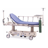
Hill-Rom P8005 Service Manual (444 pages)
Transport, Procedural, and Specialty Stretchers
Brand:
Hill-Rom
| Category:
Medical Equipment
| Size: 11.35 MB
Table of Contents
Table of Contents
5
Chapter 1: Introduction
15
Purpose
15
Audience
15
Reference Documents
15
Document Symbols
16
Specifications
17
Physical Description
17
Electrical Specification
20
Environmental Conditions
20
Regulations, Standards, and Codes
22
Electromagnetic Emissions and Immunity Guidance
25
Model Identification
29
Safety Tips
30
Warning and Caution Labels
36
Chapter 2: Troubleshooting Procedures
37
Getting Started
37
Initial Actions
37
Scale-Problem and Solution Table
38
Function Checks
39
Brake/Steer
39
Hilow and Trendelenburg/Reverse Trendelenburg
39
Siderail
40
Back Section-Procedural (Without the Auto Cotour™ Feature), Transport, Trauma, or OB/GYN Stretcher Only
40
Push Handles (Optional)
40
Active Brake System (Optional)
41
Permanent IV Pole (Optional)
41
Scale (Optional)
41
Specific Function Checks-Procedural Stretcher
42
Knee Section (Optional)-Procedural Stretcher Only
42
Auto Contour™ Feature (Optional)-ON and off (Serial Numbers (S/N)
42
Before those that Start with K)
42
Features (Optional)
42
Specific Function Checks-Surgical Stretcher
43
Back Section
43
Headrest
43
Specific Function Checks-Electric Stretcher
43
Patient Controls (Located on the Siderails)
43
Nurse Controls (Located at the Foot End of the Stretcher)
45
Manual Back Section Articulation
46
Manual Knee Section Articulation
46
CPR Release
46
Trauma Stretcher Function Checks
47
Cassette Lift
47
OB/GYN Stretcher Function Checks
47
Foot Support
47
Foot Section
47
Final Actions
47
Reduced Braking Ability
48
Loss of Corner Steer
49
Steering Plus™ Steering System Does Not Operate Correctly
50
Stretcher will Not Go into Neutral Position
51
Reduced Pedal Pumps
52
Stretcher will Not Lower
53
Siderail Does Not Operate Correctly
55
Procedural (Without the Auto Contour™ Feature), Transport, Trauma, or OB/GYN Stretcher-Back Section Does Not Raise or Lower Correctly
56
Push Handle Malfunction
57
Permanent IV Pole Does Not Raise or Lower Correctly
58
Procedural or Surgical Stretcher-Knee Section will Not Raise or Lower
59
Scale Display Does Not Come on
60
The Weight Shown on the Scale Display Is Not Correct
61
The Weight Shown on the Scale Display Is Flashing
62
The Scale Display Flashes Hands Off, then CALC, and then
63
The Scale Display Flickers or Shows Partial Characters
64
Procedural Stretcher-Auto Contour™Feature with On/Off Controls
65
Does Not Raise or Lower Correctly
65
Procedural Stretcher-Auto Contour™ Feature or Backsaver Fowler® Feature Does Not Raise or Lower Correctly
66
Surgical Stretcher Back Section-Release Handle/Gas Spring Malfunction
67
Surgical Stretcher Articulating Headrest-Push Handle Release/Gas
68
Spring Malfunction
68
Electric Stretcher-Back Section Does Not Raise or Lower Electrically
69
Electric Stretcher-Knee Section Does Not Raise or Lower Electrically
70
Electric Stretcher Back Section-Manual Articulation
71
Electric Stretcher Knee Section-Manual Articulation
72
Trauma Stretcher Cassette Lift Handle Malfunction
73
OB/GYN Stretcher-Foot Supports Malfunction
74
OB/GYN Stretcher-Foot Section Does Not Release Correctly
76
Error 0 Shows on the Scale Display
77
Error 1 Shows on the Scale Display
78
Error 2 Shows on the Scale Display
79
Error 3 Shows on the Scale Display
80
Error 5 Shows on the Scale Display
81
Error 6 Shows on the Scale Display
82
Active Brake System-Reduced Braking Ability
83
Chapter 3: Theory of Operation
85
Electrical System (Electric Stretcher)
85
Control Board
85
Power Supply
85
Input Circuit
86
Logic
86
Comparator Circuit
86
LED Outputs
87
Relay Outputs
87
Potentiometer Calibration Board
87
Electric Stretcher Wiring Diagrams
88
Scale System (Optional for the Procedural, Electric, and Trauma Stretchers)
90
Load Beams
90
Scale P.C. Board
90
Display P.C. Board
91
Display Membrane Switch Panel
92
Chapter 4: Removal, Replacement, and Adjustment Procedures
95
Tool and Supply Requirements
95
Procedural (P8000), Surgical (P8010), Trauma (P8040), or OB/GYN (P8050) Stretcher-Siderail
97
Switch the Procedural (P8000) or Trauma (P8040) Stretcher Siderail to the Opposite Side of the Stretcher
100
Electric (P8020) Stretcher-Siderail
101
Transport (P8005) Stretcher-Siderail Latch
105
Transport (P8005) Stretcher-Siderail Tube
107
Procedural (P8000), Surgical (P8010), Electric (P8020), Trauma (P8040), or OB/GYN (P8050) Stretcher-Siderail Latch
109
Procedural (P8000), Surgical (P8010), Electric (P8020), Trauma (P8040), or OB/GYN (P8050) Stretcher-Siderail Tubes
111
OB/GYN (P8050) Stretcher-Patient Grip Handle
115
Upright Tube
117
Electric (P8020) Stretcher-Patient Control Switch
121
Electric (P8020) Stretcher-Nurse Control Switch
123
Electric (P8020) Stretcher-Control Board
125
Electric Stretcher-Potentiometer
128
Electric Stretcher-Power Cord Assembly
132
Procedural (P8000), Transport (P8005), Trauma (P8040), or OB/GYN (P8050) Stretcher-Back Section Gas Spring
135
Surgical (P8010) Stretcher-Back Section Gas Spring
139
Surgical (P8010) Stretcher-Articulating Headrest Gas Spring
142
Procedural (P8000) or Surgical (P8010) Stretcher-Knee Screw Assembly
145
Electric (P8020) Stretcher-Knee Drive Assembly
147
Electric (P8020) Stretcher-Head Drive Assembly
150
Electric (P8020) Stretcher-CPR Release Cable Assembly
154
Upper Frame and Base Shroud
158
OB/GYN (P8050) Stretcher-Upper Frame Catch Shroud
163
OB/GYN Stretcher-Foot Support Mechlok® Device
165
OB/GYN Stretcher-Foot Support Gas Spring
168
Caster
172
Caster Brake Adjustment
174
Brake/Steer Pedal Adjustment
175
Hydraulic Cylinder
176
Steering Plus™ Steering System Assembly
182
Electric Stretcher-Fuse
186
Scale-Batteries
188
Scale-Load Beam
190
Scale-Display or Scale P.C. Board
203
Active Brake System
205
Active Brake System-Neutral Detent
208
Stow-Away Push Handle (Stretchers with the Integrated Oxygen Tank Storage)
210
Chapter 5: Parts List
213
Service Parts Ordering
213
Exchange Policy
215
In-Warranty Exchanges
215
Out-Of-Warranty Exchanges
216
Warranty
217
Recommended Spare Parts
219
Caster and Base Shroud
220
Base Assembly-Side Pedal
222
Base Assembly-Side Pedals with End Brake and Steer
226
Base Assembly-End Pedals
230
Base Assembly-Steering Plus™ Steering System
234
Upper Frame Assembly-Transport (P8005) Stretcher
236
Upper Frame Assembly-Procedural (P8000) Stretcher
240
Upper Frame Panel Assembly-Procedural (P8000) Stretcher
244
Upper Frame Assembly-Surgical (P8010) Stretcher
248
Surgical (P8010) Stretcher-Articulating Headrest
252
Upper Frame Assembly-OB/GYN (P8050) Stretcher (Sheet 1 of 2)
254
Upper Frame Assembly-OB/GYN (P8050) Stretcher (Sheet 2 of 2)
258
Upper Frame Panel Assembly-OB/GYN (P8050) Stretcher
260
Upper Frame Assembly-Trauma (P8040) Stretcher
264
Upper Frame Panel Assembly-Trauma (P8040) Stretcher
268
Upper Frame Labels-Trauma (P8040) Stretcher
270
Upper Frame Assembly-Electric (P8020) Stretcher
272
Electric (P8020) Stretcher-Mattress Weldment
276
Electric (P8020) Stretcher-Head and Knee Drive Assembly
278
Electric (P8020) Stretcher-Head Drive/Cpr Assemblies
280
Electric (P8020) Stretcher-Gearbox Assembly
282
Electric (P8020) Stretcher-Cable/Wire Routing
284
Electric (P8020) Stretcher-Cable/Wire Assemblies
286
Electric (P8020) Stretcher-Control Board Assembly (120 V AC and
288
Upper Frame-Auto Contour™ and Backsaver Fowler® Features
290
(S/Ns before J134AN7176 (Sheet 1 of 2))
290
(S/Ns before J134AN7176 (Sheet 2 of 2))
292
Upper Frame-Auto Contour™ and Backsaver Fowler® Features
292
(S/Ns J134AN7176 and after (Sheet 1 of 2))
296
Upper Frame-Auto Contour™ and Backsaver Fowler® Features (S/Ns J134AN7176 through those that Start with K (Sheet 2 of 2))
298
Upper Frame-Auto Contour™ and Backsaver Fowler® Features
298
(S/Ns that Start with K and After)
302
Scale System
306
Active Brake System
308
Integrated Oxygen Tank Storage System
310
Stow-Away Push Handles and Utility Tray (Stretchers with the Integrated Oxygen Tank Storage)
312
Procedural (P8000) and Trauma (P8040) Stretchers-Siderail Assembly
314
Surgical (P8010) Stretcher-Siderail Assembly
318
Electric (P8020) Stretcher-Siderail Assembly
322
OB/GYN (P8050) Stretcher Siderail-Assembly
326
Pole Module
330
Pole
332
Head/Footboard-P4120CT
334
Convertible Footboard-P350CT
336
Transporter-P491
338
IV Transporter—P491
338
Liquid Oxygen Tank Holder-P273
340
Oxygen Tank Holder-P276
341
Oxygen Tank Holder Bracket-P27604
342
Horizontal Oxygen Tank Holder-P27603
343
ISS Socket Adapter-P163
344
Pole-P2217 and ISS Transfer Pole-P158
346
IV Pole—P2217 and ISS Transfer Pole—P158
346
Security Straps-P349
348
Push Handles
350
Armboard-P344AT
352
Stirrup Assembly-P347AT
354
Trauma Stretcher Upright Chest Assembly-P279AT
356
Trauma Stretcher Lateral Cassette Holder-P264
358
Surgical Stretcher PACU Extender-P261
360
Surgical Stretcher Head Positioning Strap-P449
363
Surgical Stretcher Superior Wrist Rest-P262A01
364
Surgical Stretcher Temporal Wrist Rest-P262A02
366
OB/GYN Stretcher Integrated Fiber Optic Exam Light-P7915AT
368
OB/GYN Stretcher Placenta Basin-P265
370
OB/GYN Stretcher Telescoping Calf Support-P35745AT
372
Hill-Rom® Transport, Procedural, and Specialty Stretchers Service Manual (144386 REV 2)
374
Mattresses
374
Chapter 6: General Procedures
375
Cleaning and Care
375
General Cleaning
375
Steam Cleaning
376
Cleaning Hard to Clean Spots
376
Disinfecting
376
Spray Wash (Not Applicable to Electric (P8020) Stretcher, OB/GYN (P8050) Stretcher with the Optional Exam Light Installed)
377
Mattress Draping (OB/GYN Stretcher)
378
Component Handling (Electric Stretcher and Stretchers with the Scale Option)
378
Boards
379
Preventive Maintenance
379
Preventive Maintenance Schedule
380
Preventive Maintenance Checklist
387
Chapter 7: Accessories
389
Stretcher Accessories
389
Infusion Support System (ISS) Transfer Pole (P158)
391
Pole (P2217)
392
Permanent IV Pole
393
Patient Tray (P490)
394
Footboard (P4120CTM07)
395
Convertible Footboard (P350CT)
396
Transporter (P491)
398
Oxygen Tank Holder (P27601)
401
Liquid Oxygen Tank Holder (P273)
402
Push Handles
403
Chart Holder (P361)
405
Transport Straps (P349)
406
Utility Tray (P297A01/A02)
407
Armboard (P344BT)
409
Upright Chest Cassette Holder (P279AT)
411
Lateral Cassette Holder (P264)
414
Ankle Stirrups (P347AT)
415
PACU Extender (P261)
417
Superior Wrist Rest (P262A01)
419
Temporal Wrist Rest (P262A02)
421
Gas Delivery System (P263)
423
Head Positioning Strap (P449)
425
Placenta Basin (P265)
427
Telescoping Calf Supports (P35745AT)
429
Integrated Fiber Optic Exam Light (P7915AT)
432
Headboard Assembly (P4120CT)
439
Foot Extender Pad (P929G1/2)
440
Advertisement
Hill-Rom P8005 Service Manual (165 pages)
Stretcher
Brand:
Hill-Rom
| Category:
Medical Equipment
| Size: 2.25 MB
Table of Contents
Table of Contents
4
Chapter 1: Introduction
12
Purpose
12
Audience
12
Organization
12
Chapter 2: Troubleshooting Procedures
12
Chapter 3: Theory of Operation
12
Chapter 4: Removal, Replacement, and Adjustment Procedures
12
Chapter 5: Parts List
12
Chapter 6: General Procedures
13
Chapter 7: Accessories
13
Typographical Conventions
14
Introduction
15
General Description
15
Operating Precautions
15
Stretcher Positions
15
Specifications
21
Physical Description
21
Brake/Steer
22
Hilow
22
Siderails
22
Stretcher Back Section Inclination
22
Trendelenburg/Reverse Trendelenburg
22
Bumpers
23
IV Pole Accommodation
23
Mattress Configuration
23
Regulations, Standards, and Codes
23
Sleep Surface
23
Stretcher
23
General Operation
24
Lowering the Siderail
24
Model Identification
24
Raising the Siderail
24
Siderail Operation
24
Back Articulation
25
Hilow Operation
25
Lowering the Back Section
25
Raising the Back Section
25
Leveling the Sleep Surface
26
Quick Trendelenburg
26
Reverse Trendelenburg
26
Trendelenburg
26
Trendelenburg/Reverse Trendelenburg Operation
26
Brake
27
Central Brake and Steer
27
Steer
27
Safety Tips
28
Warning and Caution Labels
32
Chapter 2: Troubleshooting Procedures
35
Getting Started
36
Initial Actions
36
Durastar™ Hydraulic Stretcher Function Checks
37
Brake/Steer Function
37
Hilow Function
38
Trendelenburg/Reverse Trendelenburg Function
39
Siderail Function
39
Back Section Function
39
Optional Push Handle Function
39
Durastar™ Fixed Height Stretcher Function Checks
40
Brake/Steer Function
40
Siderail Function
40
Optional Push Handle Function
41
Final Actions
41
Reduced Braking Ability
42
Loss of Corner Steer
43
Stretcher will Not Go into the Neutral Position
45
Reduced Pedal Pumping
47
Stretcher will Not Lower
49
Siderail Malfunction
51
Stretcher Back Panel Does Not Go Up/Down Correctly
53
Push Handle Malfunction
54
Chapter 3: Theory of Operation
56
Chapter 4: Removal, Replacement, and Adjustment Procedures
59
Stretcher Siderail Post
60
Removal
60
Replacement
61
Stretcher Siderail Latch
62
Removal
62
Replacement
63
Stretcher Back Panel Gas Spring
65
Removal
65
Replacement
66
Adjustment
67
Durastar™ Hydraulic Stretcher Upper Frame
69
Removal
69
Replacement
70
Base Shroud Cover
71
Removal
71
Replacement
72
Caster
73
Removal
73
Replacement
76
Stretcher Hydraulic Cylinder
78
Removal
78
Replacement
81
Durastar™ Fixed Height Stretcher Upper Frame
84
Removal
84
Adjustment
87
Replacement
87
Caster Brake
89
Adjustment
89
4.10 Hydraulic Cylinder Release
91
Adjustment
91
Warranty
96
Service Parts Ordering
98
Exchange Policy
100
In-Warranty Exchanges
100
Out-Of-Warranty Exchanges
100
Recommended Spare Parts
101
Durastar™ Hydraulic Stretcher Base Assembly
103
Durastar™ Hydraulic Stretcher Upper Frame Assembly
107
Durastar™ Fixed Height Stretcher Base Assembly
111
Durastar™ Fixed Height Stretcher Upper Frame
115
IV Pole Module Assembly
119
Patient Tray-P490
121
Footboard-P4120CT
123
Convertible Footboard-P350CT
125
IV Transporter-P491
127
Oxygen Tank Holder-P276
129
Liquid Oxygen Tank Holder-P273
130
Chart Holder-P361
131
Security Straps-P349
132
Push Handles
133
Mattresses
135
Chapter 6: General Procedures
139
Cleaning and Care
140
General Cleaning
140
Steam Cleaning
140
Hard to Clean Spots
140
Disinfection
140
Lubrication Requirements
141
Preventive Maintenance
142
Preventive Maintenance Schedule
143
Preventive Maintenance Checklist
145
Tool and Supply Requirements
146
Chapter 7: Accessories
149
Accessories
150
Patient Tray
151
Installation
151
Removal
151
Footboard
152
Installation
152
Removal
152
Convertible Footboard
153
Installing as a Footboard
153
Installing as a Transport Shelf/Charting Area
154
Installing as a Foot Extender
154
Removal
154
Transporter
155
Installation
155
Oxygen Tank Holder
158
Installation
158
Liquid Oxygen Tank Holder
159
Installation
159
Push Handles
160
Installation
160
Chart Holder
162
Installation
162
Removal
163
Security Straps
164
Installation
164
Removal
164
Advertisement
Related Products
Hill-Rom P8000
Hill-Rom P8050
Hill-Rom P8010
Hill-Rom P8020
Hill-Rom P8040
Hill-Rom P870
Hill-Rom P8035
Hill-Rom RESIDENT P872
Hill-Rom P8400
Hill-Rom P8500
Hill-Rom Categories
Medical Equipment
Lifting Systems
Sling
Mobility Aid
Indoor Furnishing
More Hill-Rom Manuals
Login
Sign In
OR
Sign in with Facebook
Sign in with Google
Upload manual
Upload from disk
Upload from URL