Sign In
Upload
Manuals
Brands
High-Flying Manuals
Network Card
HF-LPT220
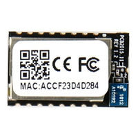
High-Flying HF-LPT220 UART Wi-Fi Module Manuals
Manuals and User Guides for High-Flying HF-LPT220 UART Wi-Fi Module. We have
2
High-Flying HF-LPT220 UART Wi-Fi Module manuals available for free PDF download: User Manual
High-Flying HF-LPT220 User Manual (65 pages)
Low Power WiFi Module
Brand:
High-Flying
| Category:
Network Card
| Size: 2.05 MB
Table of Contents
Table of Contents
4
List of Figures
8
List of Tables
9
History
10
1 Product Overview
11
General Description
11
Device Features
11
Device Paremeters
12
Key Application
12
Table 1 HF-LPT220 Module Technical Specifications
12
Hardware Introduction
13
Pins Definition
13
HF-LPT220 Pins Map
13
Table 2 HF-LPT220 Pins Definition
13
Electrical Characteristics
14
Figure 1. HF-LPT220 Mechanical Dimension
15
Figure 2. HF-LPT220 PCB Symbol Size
15
Mechanical Size
15
On-Board Chip Antenna
15
Evaluation Kit
16
External Antenna
16
Figure 3. Suggested Module Placement Region
16
Table 3 HF-LPT220 External Antenna Parameters
16
Figure 4. HF-LPT220 Evaluation Kit
17
Table 4 HF-LPT220 Evaluation Kit Interface Description
17
Figure 5. HF-LPT220 Order Informationtypical Application
18
Figure 6. HF-LPT220 Hardware Typical Application
18
Hardware Typical Application
18
Order Information
18
2 Functional Description
20
Wireless Networking
20
Basic Wireless Network Based on AP (Infrastructure)
20
Wireless Network Based on AP+STA
20
Figure 7. HF-LPT220 Basic Wireless Network Structure
20
Figure 8. HF-LPT220 STA Network Structure
20
Work Mode : Transparent Transmission Mode
21
UART Frame Scheme(Reserved)
21
UART Free-Frame
21
UART Auto-Frame
22
Encryption
22
Parameters Configuration
22
Firmware Update(Reserved, See
22
2.6. Firmware Update (Reserved, See Appendix C )
23
SOCKET B Function
23
Multi-TCP Link Connection(Reserved)
24
Figure 9. Socket B Function Demo
24
Figure 10. Multi-TCP Link Data Transmition Structure
24
3 Operation Guideline
25
Configuration
25
Usage Introduction
25
Software Debug Tools
25
Network Connection
25
Figure 11. STA Interface Debug Connection
25
Table 8 HF-LPT220 Web Access Default Setting
25
Default Parameter Setting
26
Module Debug
26
Figure 12. AP Interface Debug Connection
26
Figure 13. "Commtools" Serial Debug Tools
26
Figure 14. "Tcpudpdbg" Tools Create Connection
26
Typical Application Examples
27
Wireless Control Application
27
Figure 15. "Tcpudpdbg" Tools Setting
27
Figure 16. "Tcpudpdbg" Tools Connection
27
Figure 17. Wireless Control Application
27
Remote Management Application
28
Transparent Serial Port Application
28
Figure 18. Remote Management Application
28
Figure 19. Transparent Serial Port Application
28
4 At+Instruction Introduction
29
Configuration Mode
29
Switch to Configuration Mode
29
Figure 20. HF-LPT220 Default UART Port Parameters
29
Figure 21. Switch to Configuration Mode
29
At+Instruction Set Overview
30
Instruction Syntax Format
30
Figure 22. "AT+H" Instruction for Help
30
At+Instruction Set
31
Table 9 Error Code Describtion
31
Table 10 At+Instruction Set List
31
At+E
33
At+Wmode
34
At+Entm
34
At+Tmode
34
At+MID
34
At+Ver
35
At+Lver
35
At+Fwsz
35
At+Reld
35
At+Fclr
35
At+Z
36
At+H
36
At+Cfgtf
36
At+Uart
36
At+Uartf
37
At+Uartft
37
At+Uartfl
37
At+Uartte
38
At+Send
38
At+Recv
38
At+Ping
38
At+Netp
39
At+Maxsk
39
At+Tcplk
40
At+Tcpto
40
At+Tcpdis
40
At+Sockb
41
At+Tcpdisb
41
At+Tcptob
41
At+Tcplkb
42
At+Sndb
42
At+Rcvb
42
At+Wsssid
43
At+Wskey
43
At+Wann
43
At+Wsmac
44
At+Wslk
44
At+Wslq
44
At+Wscan
45
At+Wsdns
45
At+Lann
45
At+Wap
45
At+Wakey
46
At+Wamac
46
At+Wadhcp
46
At+Wadmn
47
At+Walk
47
At+Walkind
47
At+Wapmxsta
48
At+Ota
48
At+Upurl
48
At+Upfile
48
At+Logsw
49
At+Logport
49
At+Upst
49
At+Disps
50
At+Ntprf
50
At+Ntpen
50
At+Ntptm
51
At+Ntpser
51
At+Wrmid
51
At+Rlden
51
At+Aswd
52
At+Mdch
52
At+Txpwr
52
At+Smtlk
53
At+Smtlkver
53
At+Wps
53
At+Wpsbtnen
54
At+Lptio
54
At+Wifi
54
At+Smem
55
At+Ndbgl
55
5 Package Information
56
Recommended Reflow Profile
56
Device Handling Instruction (Module IC SMT Preparation)
56
Figure 23. Reflow Soldering Profile
56
Table 11 Reflow Soldering Parameter
56
Shipping Information
57
Figure 24. Shipping Information
57
Appendix A: Hw Reference Design
58
HTTP at Command(Reserved)
59
At+Httpurl
59
At+Httptp
59
At+Httpph
59
At+Httpcn
60
At+Httpua
60
At+Httpdt
60
Appendix B: Http Protocol Transfer
59
HTTP Example
60
Sending HTTP Raw Data in Throughput Mode(Recommend)
61
Sending HTTP Request by at Command(Reserved)
62
Appendix D:references
64
D.1.High-Flying Mass Production Tool
64
D.2.Smartlink APP V7 Config Tool
64
D.3.EVK Quick Start Guide
64
C.4.Module Upgrade
64
D.4.SDK Download
64
Appendix E: Contact Information
65
Advertisement
High-Flying HF-LPT220 User Manual (56 pages)
Brand:
High-Flying
| Category:
Wireless Router
| Size: 2.19 MB
Table of Contents
Table of Contents
2
List of Figures
5
List of Tables
6
History
7
Product Overview
8
General Description
8
Device Features
8
Device Paremeters
9
Key Application
9
Hardware Introduction
10
Pins Definition
10
Figure 1. HF-LPT220 Pins Map
10
Electrical Characteristics
12
Mechanical Size
12
Figure 2. HF-LPT220 Mechanical Dimension
12
On-Board Chip Antenna
13
External Antenna
13
Figure 3. HF-LPT220 PCB Symbol Size
13
Figure 4. Suggested Module Placement Region
13
Evaluation Kit
14
Figure 5. LPT120/LPT220 EVK
14
Order Information
15
Figure 6. HF-LPT220 Order Informationtypical Application
15
Hardware Typical Application
16
Figure 7. HF-LPT220 Hardware Typical Application
16
Functional Description
18
Wireless Networking
18
Basic Wireless Network Based on AP (Infrastructure)
18
Wireless Network Based on STA
18
Figure 8. HF-LPT220 Basic Wireless Network Structure
18
Figure 9. HF-LPT220 STA Network Structure
18
Work Mode : Transparent Transmission Mode
19
Encryption
19
Parameters Configuration
19
Firmware Update
20
SOCKET B Function
20
Multi-TCP Link Connection (Reserved)
20
Figure 10. Socket B Function Demo
20
Figure 11. Multi-TCP Link Data Transmition Structure
21
Operation Guideline
22
Configuration
22
Open Web Management Interface
22
Figure 12. Open Web Management Page
22
System Page
23
Work Mode Page
23
Figure 13. System Web Page
23
Figure 14. Work Mode Page
23
STA Setting Page
24
Figure 15. STA Setting Page
24
Figure 16. STA Scan Page
24
AP Setting Page
25
Other Setting Page
25
Figure 17. AP Setting Page
25
Figure 18. Other Setting Page
25
Account Management Page
26
Upgrade Software Page
26
Restart Page
26
Figure 19. Account Page
26
Figure 20. Upgrade SW Page
26
Restore Page
27
Internal Webpage
27
Figure 21. Restart Page
27
Figure 22. Restore Page
27
Usage Introduction
28
Software Debug Tools
28
Network Connection
28
Default Parameter Setting
28
Figure 23. Internal Webpage
28
Figure 24. STA Interface Debug Connection
28
Figure 25. AP Interface Debug Connection
28
Module Debug
29
Figure 26. "Commtools" Serial Debug Tools
29
Figure 27. "Tcpudpdbg" Tools Create Connection
29
Typical Application Examples
30
Wireless Control Application
30
Remote Management Application
30
Figure 28. "Tcpudpdbg" Tools Setting
30
Figure 29. "Tcpudpdbg" Tools Connection
30
Figure 30. Wireless Control Application
30
Transparent Serial Port Application
31
Figure 31. Remote Management Application
31
Figure 32. Transparent Serial Port Application
31
At+Instruction Introduction
32
Configuration Mode
32
Switch to Configuration Mode
32
Figure 33. HF-LPT220 Default UART Port Parameters
32
Figure 34. Switch to Configuration Mode
32
At+Instruction Set Overview
33
Instruction Syntax Format
33
Figure 35. "AT+H" Instruction for Help
33
At+Instruction Set
34
At+E
36
At+Wmode
36
At+Entm
36
At+MID
36
At+Ver
37
At+Bver
37
At+Reld
37
At+Fclr
37
At+Z
37
At+H
37
At+Cfgtf
38
At+Uart
38
At+Netp
39
At+Maxsk
39
At+Tcplk
39
At+Tcpto
40
At+Tcpdis
40
At+Sockb
40
At+Tcpdisb
41
At+Tcptob
41
At+Tcplkb
42
At+Wsssid
42
At+Wskey
42
At+Wann
43
At+Wsmac
43
At+Wslk
44
At+Wslq
44
At+Wscan
44
At+Lann
44
At+Wap
45
At+Wakey
45
At+Wadhcp
45
At+Walk
46
At+Walkind
46
At+Wapmxsta
46
At+Ota
47
At+Upurl
47
At+Disps
47
At+Plang
48
At+Webu
48
At+Wrmid
48
At+Aswd
48
At+Smtlk
49
At+Smem
49
At+Ndbgl
49
Package Information
51
Recommended Reflow Profile
51
Device Handling Instruction (Module IC SMT Preparation)
51
Figure 36. Reflow Soldering Profile
51
Shipping Information
52
Figure 37. Shipping Information
52
Appendix A: Hw Reference Design
53
Appendix B: Http Protocol Transfer
54
Sending HTTP Raw Data in Throughput Mode
54
Appendix C:references
55
C.1.High-Flying Mass Production Tool
55
C.2.Smartlink APP V7 Config Tool
55
C.3.EVK Quick Start Guide
55
C.4.Module Upgrade
55
C.5.Other Tools
55
C.6.SDK Software Develop Kit
55
Appendix D: Contact Information
56
Advertisement
Related Products
High-Flying HF-LPT100F
High-Flying HF-LPT100S
High-Flying HF-LPT100
High-Flying HF-LPT270
High-Flying HF-LPT270-1
High-Flying HF-LPT270-0
High-Flying HF-LPT271
High-Flying HF-LPT272
High-Flying HF-LPT120G
High-Flying HF-LPT170
High-Flying Categories
Wireless Router
Control Unit
Wireless modules
Network Card
Solar panel
More High-Flying Manuals
Login
Sign In
OR
Sign in with Facebook
Sign in with Google
Upload manual
Upload from disk
Upload from URL