Sign In
Upload
Manuals
Brands
HANYOUNG NUX Manuals
Temperature Controller
NP200
HANYOUNG NUX NP200 Manuals
Manuals and User Guides for HANYOUNG NUX NP200. We have
1
HANYOUNG NUX NP200 manual available for free PDF download: User Manual
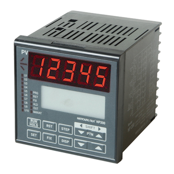
HANYOUNG NUX NP200 User Manual (75 pages)
PROGRAMMABLE TEMPERATURE CONTROLLER
Brand:
HANYOUNG NUX
| Category:
Temperature Controller
| Size: 7.07 MB
Table of Contents
Table of Contents
3
1 Safety Cautions
4
Product View
6
Key Features & Benefits
6
2 Model Code
7
3 Wiring
7
4 Dimensions
7
5 Input & Output
8
Input Signal and Measurement Range
8
Output Type
8
6 Part Name and Functions
9
Description of LED Display
9
Front Panel Key Functions
10
LCD Displays
11
Operating Display
11
Set Value (SV) Display
11
Output (OUT) Display
12
Graph Display
13
User Output Display
13
Auto & Manual Display
14
Power-On Display
14
Menu Display
14
7 Menu Display
16
Program Menu (PROG)
20
Setting Guidline
20
File Group (G.FILE)
21
Operating Menu (OPER)
22
PID Group (G.PID)
22
Control Group (G.CONTROL)
23
Function Menu (FUNC)
23
Inner Signal Group (G.IS)
23
Set Value Group (G.SV)
23
Alarm Group (G.ALARM)
24
Retransmission Group (G.TRANS)
24
User Output Group (G.UO)
24
Communication Group (G.COMM)
25
Output Group (G.OUT)
25
Setup Menu (STUP)
25
Input Group (G.IN)
26
Lock Group (G.LOCK)
26
9 Initial Setting Description
27
9-1.Menu Display
27
Input Sensor Set up
28
Select Output Type to SSR
28
Setting Example
28
Program
29
G.alarm
31
ALARM 2 Is Set to the High Limit Deviation Alarm
32
Setting Group: G.ALARM
32
Inner Signal
33
User Output
34
AT: Auto Tuning
34
10 Menu (Group) Setting Description
35
Program Menu
35
Repeat Set
36
Time Signal Mode (TS.MD)
36
Start Set Value
38
First Soak at Segment-2
38
First Soak at Segment-3
39
No Soak Segment in the Program
39
Only Ascending Ramp Segments
39
Pattern End Segment (END.SEG)
40
Pattern End Mode (END.MD)
40
Pattern End Signal Time (END.TM)
40
Link Pattern Number (LINK.PT)
41
Recording and Change of Program (Update Confirm)
41
PID Number Select (PID NO. Select)
41
Alarm Number Set (ALM NO. Select)
41
Hold
42
Step
42
Program Time Set
42
Segment Time Signal-1 (Time Signal 1)
42
Number of Patterns and Segments Being Used (INFORM)
43
Pattern Edit (PT. EDIT)
43
Segment Edit (SEG. EDIT)
43
Edit Error
43
Pattern Graph (PTN-1)
44
Time Signal (TS), Wait, and Hold
44
Time Signal (TS) and Start Mode (ST.MD)
44
Time Signal (TS) Graph
45
Operation Mode at the Error Occurrence
45
Burn-Out
45
Cold Junction Compensation (RJC), OVER, and Communication Error
45
Operation Menu (OPER)
46
Auto Tuning Group (G.AT)
46
Quick Group (G.QUICK)
46
Standard Auto-Tuning (AT.MD=STD)
46
Low PV Auto-Tuning
47
Auto-Tuning Description
47
Anti-Reset Wind up (ARW)
48
Control Output Calculation
48
Heating/Cooling Control
49
PID Control (Heating/Cooling Control)
49
Fixed Control Setting Group (G.SV)
50
Control Group (G.CTL)
50
SV (Set Value)
50
Initialization and Data Change
50
Time Unit
51
Digital Input (DI)
52
Modes at the Power Outage and Recovery
52
Inner Signal Mode (IS.MD)
53
Inner Signal Parameter Description
53
Function Menu
53
Alarm Mode (AL.MD)
56
Alarm Type
56
Alarm Functions
56
User Output (UO) Parameters
57
Retransmitting Output (RET)
58
Retransmission Range
58
RET Scale
58
Set-Up Menu (STUP)
59
Setting Menu
59
Emergency Output
60
Output Action (Direct/Reverse Action : O.ACT)
60
Hysteresis (HYS)
60
Auto and Manual Mode (A/M)
60
Sensor/Probe Input Wiring
61
Input Range
61
Burn-Out Detection
63
PV Limiter
63
PV During the A/D Error
63
Lock Functions
63
Specifications
64
Power Supply
65
Operating Environment
67
12 NP200 Communication Map
68
Communication Example
73
Advertisement
Advertisement
Related Products
HANYOUNG NUX NP100
HANYOUNG NUX Categories
Temperature Controller
Controller
Measuring Instruments
Timer
Relays
More HANYOUNG NUX Manuals
Login
Sign In
OR
Sign in with Facebook
Sign in with Google
Upload manual
Upload from disk
Upload from URL