Sign In
Upload
Manuals
Brands
GRAPHTEC Manuals
Plotter
CE7000-40
GRAPHTEC CE7000-40 Manuals
Manuals and User Guides for GRAPHTEC CE7000-40. We have
2
GRAPHTEC CE7000-40 manuals available for free PDF download: User Manual, Service Manual
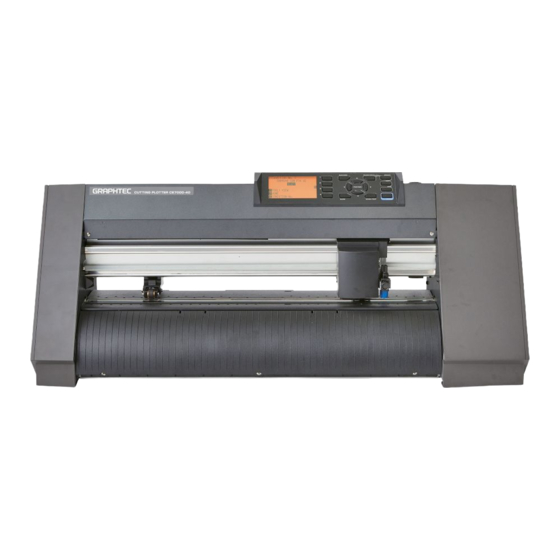
GRAPHTEC CE7000-40 User Manual (354 pages)
CUTTING PLOTTER
Brand:
GRAPHTEC
| Category:
Plotter
| Size: 10.27 MB
Table of Contents
Preface
3
Notes on this Manual
3
Registered Trademarks
3
Copyright
3
About the Words and Phrases in this Text
4
Special Precautions on Handling Blades
5
Cutter Blades
5
Cutter Plungers
5
After Mounting the Cutter Plungers
5
After Turning on the Plotter
6
Machine Caution Label
6
Notes on the Stand
6
Notes on the Basket (Option)
6
Notes on the Paper (Media)
7
Precautions When Using the Curled Media
7
Notes on the Specifications and Accessories
7
Warning
8
Use Shielded Cables
8
Installation Space
9
Selecting a Power Cable
10
Table of Contents
11
Chapter 1: Product Summary
19
Checking the Accessories
20
Accessories
20
Dedicated Accessories
21
Nomenclature
22
Front View : CE7000-40
22
Rear View : CE7000-40
23
Front View : CE7000-60
24
Rear View : CE7000-60
25
Front View : CE7000-130/160
26
Rear View : CE7000-130/160
27
Assembling
28
Mounting the Roll-Medium Tray
28
Mounting the Stock Shafts
29
Connecting to the Computer
31
Chapter 2: Preparing to Cut
33
Preparation of Cutter Plunger
34
Cutter Plunger Nomenclature
34
Structure of Cutter Plunger
35
Adjusting the Blade Length
36
Blade Application and Features
36
Attaching a Tool
37
Removing the Tool
38
Loading Media (Paper or Marking Film)
39
Loading Roll Media (CE7000-40)
39
Loading Roll Media (CE7000-60/130/160)
42
Loading Sheet Media (CE7000-40/60)
48
Loading Sheet Media (CE7000-130/160)
50
Carrier Sheet (for Affixing Media for Cutting)
53
Loading the Medium
54
Effective Cutting Area
54
Mounting the Carrier Sheet Table (Option: OPH-A45)
55
Setting Method of Carrier Sheet (Carrier Sheet Table: Option)
55
Aligning the Push Rollers
57
Aligning the Push Roller
57
When Feeding Long Media (2 Meters or More)
57
When Feeding Long Media (2 Meters or Less)
58
When Narrow Media (160 MM or Less) Is Used
58
Changing the Hold-Down Force
59
Switching
59
Assignmnent
60
About the Default Screen
61
Connecting to the Power
62
How to Use Control Panel
63
Indicator Lamp
63
Operation Key
63
Reading the Screen (LCD)
64
Contents of Operation from MENU Screen
66
Simple Mode
66
Normal Mode
67
Operation from [COND/TEST] Key
68
Simple Mode
68
Normal Mode
68
Setting Feeding Method
69
Pre Feed of Media (Paper or Marking Film)
71
Selecting Tool Condition
72
Simple Mode
72
Normal Mode
73
Setting the Tool Condition
74
Setting the Speed and Force (Simple Mode)
76
Setting the Tool
78
Setting the Speed
80
Setting the Force
82
Setting the Acceleration
83
Setting Tool no
85
Adjust the Blade Length Manually
87
Running Cutting Tests
88
Cutting Test
88
To Make 1 Cut with Set Value
88
To Make 3 Cuts with Set Value and ±1 of Set Value
89
Confirm the Results of the Cutting Test
91
Adjustment of Offset
91
Adjustment for Half Cutting
91
Adjustment for Cutting out
91
Adjustment When Using Plotting Pen
91
Adjust the Blade Length (Automatic Height Adjust)
92
About Simple Mode
95
Changing Mode
96
Setting Page Length (Simple Mode)
97
Origin Point Settings When Configuring HP-GL (Simple Mode)
99
GP-GL Step Size (Simple Mode)
100
Display Language Settings (Language) (Simple Mode)
101
Display Length Unit Settings (Length Unit) (Simple Mode)
102
Displaying Cutting Area
103
Chapter 3 : Basic Operations
106
Raise or Lower the Tool
106
Move the Tool Carriage and Media
107
Move in Steps Manually
107
Continuously Move Manually
107
Setting Step Movement Distance
108
Move Away the Tool Carriage
109
Change the Cutting Condition (Condition No.)
110
Reset (Revert to the Initial State When the Power was Turned On.)
110
Setting the Origin Point
111
When Coordinate Axes Rotation Are Set
112
When Coordinate Axes Are Rotated after Origin Point Is Set
112
Setting Origin Point When HP-GL Is Set
113
Setting the Cutting Direction
114
Stop Cutting
116
Pause and Resume Cutting
116
Stop Cutting
117
Chapter 4 : Convenient Functions
120
Settings for Cutting
120
Setting Cutting Area
120
Setting Cutting Width (EXPAND)
122
Setting Length of the Page
123
Setting Mirror
125
Set the Enlarge/Shrink Scale (Scale)
126
Copy (Duplicate Cutting)
128
When Media Change Mode Is off
128
When Media Change Mode Is on
131
Panel Cutting
133
Chapter 5: ARMS (Advanced Registration Mark Sensing System)
135
Outline of ARMS
136
Shape (Pattern) of the Registration Mark and Origin Point
137
Scan Range Necessary to Detect the Registration Mark
138
Positioning of the Media and the Registration Mark
140
Cutting Area When Adjusting the Regisitaration Mark
140
Automatic Detection of Registration Mark Position
141
Media that Registration Mark Cannot be Detected
141
Setting and Adjustment of ARMS
142
Set the MARK SCAN Mode
142
Checking the Recommended Setting of Registration Mark
144
Check the Lines of Registration Mark
146
Test the Registration Mark Sensor
148
Adjusting for the Registration Mark Scan Position
150
Adjust after Plotting the Adjustment Registration Mark
150
Detect the Registration Mark for Adjustment on the Media and Enter the Value
154
Setting the Registration Mark Automatic Detection
157
Setting Speed of the Registration Mark Scan
159
Chapter 6: Manual Position Adjust
161
Outline of Manual Position Adjust
162
Setting Mark Scan Mode and Number of Adjustment Marks
162
Adjust with 2POINTS
162
Adjust with 3POINTS
163
Adjust with 4POINTS
163
Manual Position Adjust
164
Chapter 7: Setting Regarding Cutting Quality
169
Cutting the Corner of Thick Media Sharp
170
Outline of Tangential Mode
170
Setting the Tangential Mode
171
Setting the Length of Overcut
172
Setting of the Initial down Force
174
Setting the Step Pass
176
Setting the Offset Angle
178
Setting the Distance Adjust
180
Setting Cut Line Pattern
183
Setting Initial Blade Control Position Adjust
187
Setting the OFFSET FORCE
189
Setting Adjustment between the Tools
190
In the Case of Tool 1 - Tool 3
190
Chapter 8: Settings Regarding Cutting Time
193
Sorting the Cutting Data
194
Perform Automatic Pre Feed When Cut Data Is Received
196
Perform Automatic Pre Feed When Media Is Set (Initial Feed)
198
Setting Feed Speed for Pre Feed
199
Setting the MOVING SPEED
201
Setting the Tool up Move
203
Setting the Tool up Height
205
Chapter 9: Setting Regarding Interface
207
Setting Interface
208
USB Interface
208
Network (LAN) Interface
209
RS-232C Interface
209
Clearing the Buffer Memory
210
I/F (Lan)
211
Setting the DHCP
211
Set IP Address, Subnet Mask, Gateway
213
Connecting with RS-232C
216
Switching the Setting Number You Want to Use
216
Changing/Storing the RS-232C Setting
217
Chapter 10: Settings Regarding Operation Environment
221
Related to Menu Display
222
Display Language Setting (LANGUAGE SELECTION)
222
Display Length Unit Setting (LENGTH UNIT)
223
Related to Sensor
224
Enabling/Disabling the Media Sensors (MEDIA SENSOR)
224
Enabling/Disabling the Push Roller Sensors (PUSH ROLLER SENSOR)
225
Related to Plotter Environment
227
Fan Suction Setting (FAN POWER)
227
Enabling/Disabling the Beep Setting (BEEP for KEY OPERATION)
228
Pause Key Select Setting (Selecting PAUSE Key)
229
Simple Mode / Normal Mode Setting (Simple Mode / Normal Mode)
230
LCD Contrast Setting (LCD Contrast)
231
Chapter 11: Settings of Controls from Computer
233
Related to Command Processing
234
Setting the Command (COMMAND)
234
Priority of Tool Condition Selection (CONDITION PRIORITY)
235
Related to GP-GL Command
236
Setting the Step Size (GP-GL STEP SIZE)
236
Enabling/Disabling the ' : ' and ' ; ' Commands (COMMAND ' : ', ' ; ')
237
Moving the Pen While Raised or Lowered in Response to the 'W' Command (COMMAND 'W')
238
Related to HP-GL Command
239
Model ID Response (HP-GL MODEL EMULATED)
239
Circle-Command Resolution Setting (CIRCLE RESOLUTION)
240
Chapter 12: Data Link
241
Select Connection Destination
242
Data Link with USB Memory
243
Output with a Bar Code
245
Start Mark Auto Scan
248
Communication Timeout
250
Skew Scanning
252
Chapter 13: Cutting with Supplied Application Software
255
Basic Operation of Printing and Cutting
256
Graphtec Pro Studio / Cutting Master 4
256
Graphtec Studio
265
Basic Operation of Bar Code
269
Graphtec Pro Studio / Cutting Master 4
269
Application of Barcode Cutting (Continuous Operation)
277
Graphtec Pro Studio
277
Chapter 14: Maintenance
291
Daily Maintenance
292
Storing the Plotter
292
Replacing Cutter Blade
293
Cleaning the Cutter Pen
295
Cutter Plunger Exchange
296
Setting the Alarm for Degree of Wear (BLADE WEAR ALARM)
297
Chapter 15: Troubleshooting
301
Troubleshooting
302
When the Plotter Does Not Operate after Turning the Power on
302
When It Does Not Work Right
303
When the Cutting Result Is Not Good
305
Error Messages in GP-GL Command Mode
306
Error Messages in HP-GL Command Mode
307
ARMS Error Messages
309
Other Error Messages
312
Caution Message
315
Printing the Setting of the Plotter
316
Creating Test Pattern
318
Creating CUTTING PRO
320
Confirm the Cutting Data
322
Self Diagnostic Test
324
Reading the Error Message
326
Appendix
329
Main Specifications
329
Options and Supplies
329
Supplies
331
External Dimensions
332
Menu Tree
335
Initial Setting
345
Simple Mode
345
Normal Mode
346
Index
349
Advertisement
GRAPHTEC CE7000-40 Service Manual (278 pages)
CUTTING PLOTTER
Brand:
GRAPHTEC
| Category:
Plotter
| Size: 55.79 MB
Table of Contents
Table of Contents
5
1 Introduction
11
Main Specifications
11
CE7000 Main Specifications
11
CE7000-130AP Main Specifications
12
External Dimensions
13
CE7000 External Dimensions
13
CE7000-130AP External Dimensions
16
Option & Supply Parts
17
CE7000 Option & Supply Parts
17
CE7000AP Supply Parts
17
2 Setup
18
Confirming the Standard Accessory
18
Standard Accessory for the CE7000-40/60/130/160
18
Standard Accessory for the CE7000-130AP
19
Assembling Stand and Basket to the Plotter
20
Assembling Stand for the CE7000-60
20
Assembling the Stand for CE7000-130/160
23
Assembling the Stand for CE7000-130AP
26
Installing the Optional Basket for CE7000-60
30
Installing the Optional Basket for CE7000-130/160
32
3 PARTS NAMES and FUNCTIONS
34
Parts Names and Functions for CE7000-40
34
Parts Names and Functions for CE7000-60
36
Parts Names and Functions for CE7000-130/160
38
Parts Names and Functions for CE7000-130AP
40
Attaching a Tool
42
Attaching a Tool for CE7000-40/60/130/160
42
Attaching a Tool and a Pen for CE7000-130AP
44
4 Operations
47
OPERATIONS for the CE7000-40/60/130/160
47
Control Panel for the CE7000-40/60/130/160
47
Menu Tree for CE7000-40/60/130/160
52
OPERATIONS for the CE7000-130AP
60
Control Panel for the CE7000-130AP
60
Menu Tree for CE7000-130AP
64
5 Recommended Parts List
71
6 List of Tools
73
Tools
73
Greasing and Gluing Points
73
7 Disassembly and Reassembly
75
Exterior Parts
75
Replacing the Right Side Cover
75
Replacing the Left Side Cover
75
Replacing the Control Panel Assembly
76
Replacing the Center Cover
77
Replacing the Front Guide
78
Replacing the Rear Guide
80
Replacing the Rear Writing Panel
82
Replacing the Front Writing Panel Assembly
83
Replacing the Fan Cover
84
Replacing the Pen Block Cover
85
Replacing the Push Roller
86
Replacing the Cutting Mat
87
Internal Parts
88
Replacing the Rear Media Sensor
88
Replacing the Front Media Sensor
88
Replacing the Registration Mark Sensor
89
Replacing the Control Panel Board
90
Replacing the LCD
91
Replacing the Pen Block
92
Replacing the Y-Belt
94
Replacing the Push Roller Sensor Board
98
Replacing the Y-Relay Board
99
Replacing the Cam Sensor Board
100
Replacing the Y-Motor
102
Replacing the X-Motor
105
Replacing the Main Board
109
Replacing the Fan
111
Replacing the Drive Roller Shaft for CE7000-40/60
114
Replacing the Drive Roller Shaft for CE7000-130/130AP/160
118
Replacing the y Flexible Cable
121
Detaching the Push Roller Assembly
123
Replacing the Push Roller Base
129
Replacing Power Supply Board
132
Belt Tension Adjustments
133
Y-Belt Tension Adjustment
133
Y-Drive Belt Tension Adjustment
134
X-Drive Belt Tension Adjustment
136
Confirming the Cable Wiring
138
8 Electrical Adjustment
144
List of Items Requiring Readjustment
144
Flowchart of the Adjustment Sequence
145
When the Main Board was Replaced (Normal Procedure)
145
When the Main Board was Replaced (the Adjustment Values Could Not Copy.)
146
When the Pen Block was Replaced
147
When the Rear or Front X Media Sensor was Replaced
147
When the Registration Mark Sensor was Replaced
147
When the Cam Sensor Board was Replaced
148
When the 2Nd Pen of Holder or Station was Replaced
148
When the Optional Push Roller was Installed
148
When the Gird Roller was Replaced
148
DIP Switch Settings
149
Explanation of the Values of the Main Board Settings
151
Confirming the Version of Firmware
152
Upgrading the System Firmware
153
Clearing the NOV-RAM
156
Selecting Display Language & Length Unit
158
Copying the Adjustment Value Form the SUB-NVRAM
159
How to Enter the Adjustment Menu
160
Adjusting the Pen Force
162
Inputting the Pen Force from the Recorded Value
162
Adjusting the Pen Force from the Measured Force
164
Adjusting the Distance Accuracy
167
Inputting the Distance Accuracy from the Recorded Value
167
Adjusting the Distance Accuracy from the Measured Distance
169
Adjusting the Registration Mark Sensor Sensitivity
172
Adjusting the Offset of Registration Mark Sensor
175
Inputting the Registration Mark Sensor Offset Position from the Recorded Values
175
Adjusting the Registration Mark Sensor Offset Position from the Measured Values
178
Adjusting the X Media Sensor Position
182
Inputting the X Media Sensor Position from the Recorded Value
182
Adjusting the X Media Sensor Position
185
Adjusting the 2Nd Pen Exchange Position (CE7000-130AP)
187
Inputting the 2Nd Pen Exchange Position from the Recorded Value
187
Adjusting the 2Nd Pen Exchange Position
189
Adjusting the Spacing between Tool 1 and Tool 2 (CE7000-130AP)
192
Inputting the Spacing between Tool 1 and Tool 2 from the Recorded Value
192
Adjusting the Spacing between Tool 1 and Tool 2
192
Setting the Number of Push Rollers (CE7000-130/160)
198
Back up the Adjustment Value to the SUB-NVRAM
200
9 Troubleshooting
204
The Plotter Is Turned on but Doesn't Operate
204
Media Loading Operations
205
Cutting Operations
208
Print & Cut Operation
210
USB Connection
214
Error Messages
215
Hardware Error Messages
215
Error Messages in GP-GL Command Mode
219
Error Messages in HP-GL Emulation Mode
222
Error Messages on ARMS
224
Other Error Messages
230
Warning Messages
233
Service Mode
234
Sensor & Panel Switch Test Mode
234
Printing the Setting of the Plotter
236
Printing the Test Pattern
237
Confirm the Cutting Data
238
Self Diagnostic Test
239
Registration Mark Sensor Test
241
Clear Setup Mode
243
10 Parts List
244
Outer Casing CE7000-40/60
244
Outer Casing CE7000-130/130AP/160
245
Additional Outer Casing CE7000-130AP
246
Control Panel
247
Pen Block CE7000-40/60/130/160
248
Pen Block CE7000-130AP
249
Main Electrical Parts CE7000-40/60
250
Main Electrical Parts CE7000-130/130AP/160
251
Drive Parts CE7000-40/60
252
Drive Parts CE7000-130/130AP/160
253
Y Drive Part CE7000-40/60
255
Y Drive Part CE7000-130/130AP/160
256
Y Slider Part CE7000-40/60
257
Y Slider Part CE7000-130/130AP/160
258
Stand for CE7000-60 (ST0118)
259
Stand for CE7000-130/160 (ST0119/0120)
260
Stand for CE7000-130AP (ST0121)
261
Basket for CE7000-60/130/160
262
Details of Basket Base Bracket
263
Roll Media Stoker for CE7000-40
264
Labels
265
Standard Accessories
266
11 Wiring Diagrams
267
12 Target Electrical Component for WEEE Instruction
268
Advertisement
Related Products
GRAPHTEC CE7000-130AP
GRAPHTEC CE7000 Series
GRAPHTEC CE7000-60
GRAPHTEC CE7000-130
GRAPHTEC CE7000-160
GRAPHTEC CE7000-60E
GRAPHTEC CE200-120
GRAPHTEC CE5000-40CRP
GRAPHTEC CELITE-50
GRAPHTEC CE6000-120AMO
GRAPHTEC Categories
Plotter
Data Loggers
Scanner
Cutter
Printer
More GRAPHTEC Manuals
Login
Sign In
OR
Sign in with Facebook
Sign in with Google
Upload manual
Upload from disk
Upload from URL