Sign In
Upload
Manuals
Brands
Gozuk Manuals
Inverter
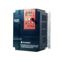
EDS1000-2S0007
Gozuk EDS1000-2S0007 Manuals
Manuals and User Guides for Gozuk EDS1000-2S0007. We have
1
Gozuk EDS1000-2S0007 manual available for free PDF download: User Manual
Gozuk EDS1000-2S0007 User Manual (185 pages)
0.4-55kW
Brand:
Gozuk
| Category:
Inverter
| Size: 2.02 MB
Table of Contents
Table of Contents
4
Safety Information and Use Notice Points
8
Safety Precautions
8
Use Range
9
Use Notice Points
9
Scrap Notice Points
10
Type and Specification of the Inverter
11
Incoming Inverter Inspect
11
Type Explanation
11
Series Type Explanation
12
Appearance and Parts Name Explanation
13
Outer Size and Gross Weight
13
Mounting Size
14
Outer Size of Key Board and Its Fixing Box
15
Product Technic Index and Spec
15
Installation and Wiring
18
Installation Direction and Space
18
Demand for Installation Ambient
18
Key Board Disassembly and Installation
19
Plastic/Metal Cover Disassembly and Installation
19
Wiring Notice Points
20
Main Loop Terminal Wiring
21
Connection between Inverter and Fitting Parts
21
Main Loop Terminal Wiring
23
Basic Running Wiring Diagram
25
Control Loop Collocation and Wiring
26
Location & Function of Terminal and Slide Switch
26
Explanation for Control CPU Board
27
CPU Board CN2 Terminal Function Table
27
CPU Board RS485 Terminal Function Table
29
Analog Input Output Terminal Wiring
30
CPU Board JP1 Terminal Function
30
CCI Terminal Wiring Diagram
30
Communication Terminal Wiring
32
Installation Guide for Anti-Jamming
34
Restraining to Noise Disturbance
34
Type of Disturbance Noise
34
Noise Spread Road
35
Disturbance Suppressing Countermeasure Table
35
Local Wiring and Earthing
36
Installation Demand for Electromagnetic On-Off Electronic Device
36
Relation of Long-Distance Wiring and Current Leak and the Countermeasure
36
Running Order Channels
38
Frequency-Provision Channel
38
Work State
38
Run and Operation Explanation for Inverter
38
Run of Inverter
38
Logic Flow Chart of EDS1000 Inverter Run State
39
Run Mode
39
Common Run
40
Multi-Section Speed Run
40
PLC Run
40
Swing Frequency Run
40
Operation and Use of Key Board
41
Keypad Layout
41
Keypad Function Description
41
LED and Indicator Light
42
Key Board Display Status
42
Waiting Parameter Display Status
42
Run Parameter Display Status
43
Failure Alarm Display Status
43
Method for Operating Keypad
44
Function Code Editing Status
44
Special Display Function
44
Function Code Parameter Setting
45
Specified Frequency Adjustment for Common Run
46
Jog Run Operation
46
Entering to Function Code Editing Status after Setting Password
46
See about Failure Parameter under Failure Status
47
Keypad Key-Press Locking Operation
47
Keypad Key-Press Unlocking Operation
47
Inverter Electrification
48
Check before Electrification
48
First Electrification
48
5 Function Parameter Schedule Graph
49
Function Parameter Schedule Graph
49
Symbol Description
49
Start, Stop, Braking Function Parameter Group
50
Auxiliary Run Function Parameter Group
51
Closed-Loop Run Function Parameter Group
54
Simple PLC Function Parameter Group
56
Terminal Correlative Function Parameter Group
57
Traverse Special Function Parameter Group
60
Frequency Provision Function Parameter Group
60
Motor and Vector Control Parameter Group
61
Protection Function Parameter Group
61
Failure Record Function Parameter Group
62
Password and Manufacturer Function Parameter Group
62
Supervision Function Parameter Group
63
Stop Assistant Function Parameter Group
63
Detailed Function Description
64
Basic Run Function Parameter Group: F0
64
Frequency Input Channel Selection
64
Freq. Digit Setting
65
Run Command Channel Selection
65
Run Direction Setting
65
Acce/Dece Mode Selection
66
Acce/Dece Time Unit
66
S Curve Rising Time
66
S Curve Starting Time
66
Acce/Dece Time Definition
67
Dece Time 1
67
Torque Boost Mode
67
Upper Limit Freq./Lower Limit Freq./Lower Limit Freq. Run Mode
67
Torque Boost
68
V/F Curve Setting
68
G/P Type Setting
69
Start Run Mode
69
Start, Stop, Braking Function Parameter Group: F1
69
DC Braking Time When Starting
70
DC Braking Volt. When Starting
70
Starting Freq. Duration Time
70
Starting Frequency
70
Analog Filter Time Constant
71
Auxiliary Run Function Parameter Group: F2
71
FWD REV Run Dead-Section Time
71
Stop Mode
71
AVR Function
72
Carrier Wave Freq.
72
Slip Freq. Compensation
72
Jog Acce Time
73
Jog Dece Time
73
Jog Run Frequency
73
Relation Table of Device Type and Carrier Frequency
73
Freq. Input Channel Combination
74
LED Display Control 1/2
75
Main & Sub Inverter Communication Freq. Provision Proportion
75
Parameter Operation Control
76
Communication Configuration
77
Communication Overtime Checkout Time
77
Local Address
77
Local Response Delay Time
77
Acce Time
78
Dece Time
78
Multi-Step Freq.
78
Jumping Freq.
79
VF Frequency Value
79
VF Voltage Value
79
Closed-Loop Run Function Parameter Group: F3
80
RS485/232 Communication Frame Format Selection
80
Run Time Accumulation
80
Set Run Time
80
PID Control Principle Diagram
81
Specified Value and Expected Feedback Value
81
Closed-Loop Run Control Selection
82
Feedback Channel Selection
82
Provision Channel Selection
82
Specified Value Digital Setting/Target Pressure Value Setting
82
Corresponding Feedback Value
83
Max. Specified Value Value
83
Min. Specified Value
83
Provision Feedback Curve
83
Closed-Loop Preset Frequency/Closed-Loop Preset Frequency Holding Time
84
Deviation Limit
84
Integral Separation PID Adjusting Threshold
84
Sleep Frequency Threshold/Wake Pressure Threshold
84
Constant Pressure Water Supply Mode 1
85
Long-Distance Manometer Range
85
Revival Delay Time
85
Sleep Delay Time
85
Automatic Switchover Interval
86
Closed-Loop Adjusting Characteristic
86
LED Initial Supervision Para. Selection
86
Water Supply Supervision Para. Display
86
Failure Relay TA TB TC Function Selection
87
Simple PLC Function Parameter Group: F4
87
YCI Run-In Delay Time
87
Stop after PLC Single Circle
88
Holding Mode after PLC Single Circle
89
PLC Consecutive Circle Mode
89
PLC Starting Mode 1
90
Terminal Correlative Function Parameter Group: F5
91
Multifunction Input Function Selection Table
92
Multi-Step Speed Run Selection Table
93
Acce & Dece Time Terminal Selection
94
Terminal Frequency Provision Channel Selection Logic Mode
96
Run Command Channel Logic Mode
97
FWD/REV Run Mode Selection
98
Open Circuit Collector Output Terminal OC1-OC4 Output Setting
99
Output Terminal Function Selection Table
99
UP/DOWN Velocity
99
Analog Output Selection
102
FDT1 (Freq. Level) Electric Level/Fdt1 Lag
102
Freq. Arriving (FAR) Detect Range
102
DO Max. Pulse Output Freq.
103
DO Terminal Output Function Selection
103
Set Interior Count Number Arriving Provision
103
Specified Interior Count Number Arriving Provision
103
Sudden Jumping Freq.
104
Traverse Function Selection
104
Traverse Run Mode/Traverse Amplitude Threshold
104
Traverse Special Function Parameter Group: F6
104
Traverse Cycle
105
Traverse Preset Frequency
105
Triangle Wave Rising Time
105
Frequency Provision Function Parameter Group: F7
106
Control Mode Setting
108
Motor and Vector Control Parameter Group: F8
108
Failure Self-Renew Interval
110
Failure Self-Renew Times
110
Motor Overload Protection Mode Selection
110
Protection Function Parameter Group: F9
110
Motor Overload Protection Coefficient
111
Overload Warning Alarm Checkout Level
111
Overload Warning Alarm Delay Time
111
Overvoltage Stall Selection/Overvoltage Stall Point
111
Failure Record Function Parameter Group: Fd
113
Password and Manufacturer Function Parameter Group: FF
114
Stop Assistant Function Parameter Group: FA
115
Troubleshooting
116
Failure and Countermeasure
116
Failure Record Lookup
118
Failure Reset
119
Inspection and Replacement of Damageable Parts
120
Daily Inspection Items
120
Routine Maintenance
120
Storage
121
Repair Guarantee
121
Fitting Parts
122
Communication Subassembly
122
Long-Distance Operation Key Board
122
Communication Cable
122
Examples
123
Common Speed Regulation Running
123
Terminal Control Running
124
Multi-Step Speed Control Running
125
Closed-Loop Control System
126
Consecutive Action Running
127
Application to Constant Pressure Water Supply
128
Constant Pressure Water Supply Control and Its Mode
129
Connection between Water Supply Controller and Inverter
129
Function Parameter Setting for Constant Pressure Water Supply
130
Setting Steps and Basic Wiring Diagram
132
Serial Port RS485 Communication Protocol
134
Communication Net Buildup Mode
134
Communication Mode
134
Data Command Frame Format
135
Explanation and Description for Format
136
Response Code Meanings for Command Code "10"
136
Response Code Meanings for Command Code “11~15”
136
Failure Type Description
137
Protocol Command List
138
Response State Word Meanings of Reading Inverter State Command
140
Read Auxiliary Device Function Code Parameter
141
Set Auxiliary Device Function Code Parameter
142
Drawing Machine Schematic Diagram
143
Drawing Machine Working Theory
144
Working Requirements (Drawing Machine)
144
Feedback Polarity Detection
144
Jog Lead Wire
145
Maximum Frequency
145
Smoothly Start up for Wire Retracting Machine
145
Volume Diameter Automatically Calculate Time Interval
146
Dead Zone Range When Automatically Volume Calculation
146
Automatically Volume Diameter Calculation
146
EDS1100 Series Inverter Model No. and Specification
147
Volume Diameter Reset
147
Drawing Machine Tension Control
147
Control Wiring
147
EDS1100 Series Inverter Technique Index and Specifications
148
Function Code Schedule Graph Especially for Drawing Machine
150
Wiring of Host and Wire Retracting Machine
155
Wiring for Wire Retracting Machine Feedback
156
Wiring for Brake Resistance
156
Host Parameters of Big and Medium Drawing Machine
157
Wire Receiving Machine Parameters of Big and Medium Drawing Machine
157
Host Parameters of Fine-Drawing Machine and Micro-Pulling Machine
159
Wire Receiving Machine Parameters Fine-Drawing/Micro-Pulling Machine
160
The Manual of EDS1300 Middle Frequency Inverter
162
Basic Run Function Parameter Group
162
Start, Stop, Brake Function Parameter Group
163
Swing Frequency Special Function Parameter Group
172
Protection Correlative Function Parameter Group
174
Modbus Communication Protocol
176
Communication Mode
176
RTU Communication Mode
177
Data Frame Format
177
Host Read Slave Parameter
178
Host Write Slave Parameter
178
Data Communication Address Allocation
179
Function Code Fd-F0 Group Communication Address
179
Control Command and Status Word Communication Address
179
Monitor Parameter Communication Address
180
Communication Error Processing
181
Data Frames Examples
182
CRC Checksum Mode
183
Braking Resistance
184
Advertisement
Advertisement
Related Products
Gozuk EDS1000-2S0004
Gozuk EDS1000-2S0015
Gozuk EDS1000-2S0022
Gozuk EDS1000-2S0037
Gozuk EDS1000-4T0055G/0075P
Gozuk EDS1000-4T0075G/0110P
Gozuk EDS1000-4T0185G/0220P
Gozuk EDS1000-4T0300G/0370P
Gozuk EDS1000-4T0550G/0750P
Gozuk EDS1000-7T0110G/0150P
Gozuk Categories
Inverter
More Gozuk Manuals
Login
Sign In
OR
Sign in with Facebook
Sign in with Google
Upload manual
Upload from disk
Upload from URL