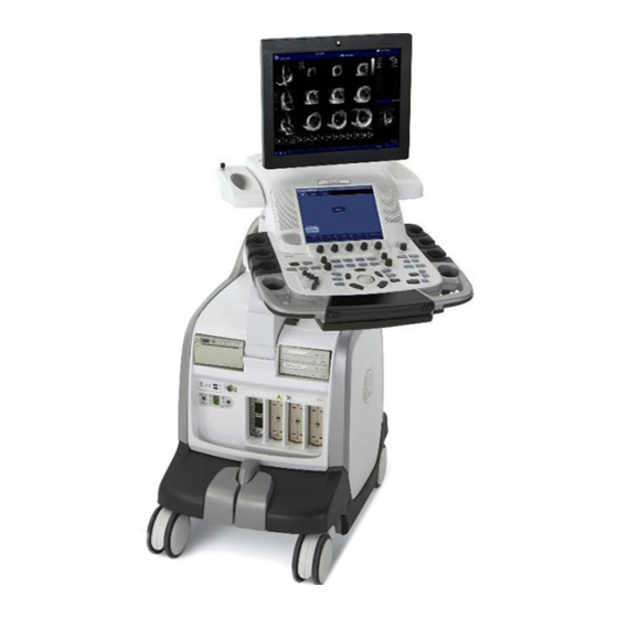
Sign In
Upload
Manuals
Brands
GE Manuals
Medical Equipment
Vivid E9
GE Vivid E9 Manuals
Manuals and User Guides for GE Vivid E9. We have
3
GE Vivid E9 manuals available for free PDF download: Service Manual, Quick Reference Cards
GE Vivid E9 Service Manual (802 pages)
Brand:
GE
| Category:
Medical Equipment
| Size: 46.44 MB
Table of Contents
Table of Contents
15
CHAPTER 1 Introduction
35
Overview
35
Purpose of this Chapter
35
Contents in this Chapter
35
Service Manual Overview
36
Contents in this Service Manual
36
Typical Users of the Service Manual
36
Overview
36
VIVID E9 Models Covered by this Manual
37
Product Description
39
Important Conventions
40
Conventions Used in this Book
40
Standard Hazard Icons
41
Product Icons
42
Safety Considerations
45
Introduction
45
Human Safety
45
Mechanical Safety
47
Electrical Safety
49
Labels Locations
50
Label on Front of LCD Monitor
50
Label on Rear of LCD Monitor
50
Label on Upper OP Panel
51
Labels on Front Handle
51
Labels on Top of Console
51
Labels Near Connectors on Front
52
Labels on DVD Units
53
Label on External I/O
53
Labels at AC Mains Inlet and Circuit Breaker
54
Label on Rear Cover
55
Label on Rear Cover - Detailed Descriptions
60
Label on the Bep6'S Door
63
Label on the Bep5'S Door
64
Label, Disassembly Nester
65
Dangerous Procedure Warnings
66
Lockout/Tagout (LOTO) Requirements
67
Returning/Shipping Probes and Repair Parts
67
Electromagnetic Compatibility (EMC)
68
What Is EMC
68
Compliance
68
Electrostatic Discharge (ESD) Prevention
68
Customer Assistance
69
Contact Information
69
System Manufacturer
70
CHAPTER 2 Site Preparations
71
Overview
71
Purpose of this Chapter
71
Contents in this Chapter
71
General Console Requirements
72
Console Environmental Requirements
72
Electrical Requirements
74
EMI Limitations
77
Probes Environmental Requirements
78
Time and Manpower Requirements
78
Facility Needs
79
Purchaser Responsibilities
79
Required Facility Needs
80
Desirable Features
81
Minimal Floor Plan Suggestion
81
Suggested Floor Plan, VIVID E9 and Echopac PC in same Room
81
Networking Setup Requirements
82
CHAPTER 3 System Setup
85
Overview
85
Purpose of this Chapter
85
Contents in this Chapter
85
Setup Reminders
86
Average Setup Time
86
Setup Warnings
86
Receiving and Unpacking the Equipment
87
Purpose of this Section
87
Receiving and Unpacking Warnings
87
The Tilt & Shock Indicators
88
Receiving the VIVID E9
89
Unpacking VIVID E9 from the Wooden Box
94
Unpacking VIVID E9 from the Carton Box
96
Packing Materials for the Wooden Box - Recycling Information
100
Packing Materials for the Carton Box - Recycling Information
101
Preparing for Setup
103
Verify Customer Order
103
Physical Inspection
103
EMI Protection
103
Completing the Setup
104
Purpose of this Section
104
System Specifications
104
Electrical Specifications
105
Connections on the External IO
106
Connections on the Patient I/O Panel
107
Connecting Probes
108
Power On/Boot up
110
Power Shut down
110
Configuration
111
Purpose of this Section
111
VIVID E9 Configuration
111
Service Screen Setup
116
Optional Peripherals/Peripheral Connection
120
Direction Ga091568, Revision 5 VIVID E9 Service Manual
120
Software Options Configuration
122
Connectivity Overview
124
Physical Connection
124
Connectivity Setup
125
Introduction
125
Compatibility
125
Select TCP/IP Screen
126
Changing the AE Title And/Or Port Number (Port No.)
127
DHCP Setup
128
Set the Remote Archive's Network Information
131
Save the New Settings
132
Options Setup
133
Software Options
133
Color Video Printer (Optional) Installation
133
Setup Paperwork
134
User's Manual(S)
134
Product Locator Installation Card
135
CHAPTER 4 General Procedures and Functional Checks
137
Overview
137
Purpose of this Chapter
137
Contents in this Chapter
137
Special Equipment Required
138
General Procedures
139
Power On/Boot up
140
Power Shut down
144
Top Console Position Adjustment
147
LCD Monitor Position Adjustment
150
Logging on to VIVID E9 as 'ADM
151
Moving and Transporting the VIVID E9
153
Recording Important Settings and Parameters
155
Cleaning the Trackball from the Outside (OP-5)
167
Cleaning the Trackball (OP-1 to OP-4)
168
Functional Checks
173
Preparation
173
Mode (B Mode) Checks
173
M Mode Checks
175
Color Mode Checks
176
PW/CW Doppler Mode Checks
178
Tissue Velocity Imaging (TVI) Checks
179
Probe/Connectors Check
180
ECG Check
181
Cineloop Check
182
Back End Processor Checks
183
Operator Panel Test
183
Peripheral Checks
183
Mechanical Functions Checks
187
Site Log
188
CHAPTER 5 Components and Functions (Theory)
191
Overview
191
Purpose of this Chapter
191
Contents in this Chapter
191
Insite Exc
194
Introduction
194
Insite Exc Icon
194
Insite Exc Status
195
Initiating a Request for Service (RFS)
196
Automatic Request for Service (ARFS)
197
Insite Exc Definitions
198
Exiting Insite Exc
198
VIVID E9 Overview
199
Purpose of this Section
199
Introduction
199
VIVID E9 General Description
200
VIVID E9 Block Diagram
200
Signal Flow Overview
201
System Configuration and Software
202
The Electronics
202
VIVID E9 Interconnection Diagram
203
VIVID E9'S Operating Modes
205
Top Console with LCD Monitor and Operator Panel
207
Top Console Description
207
Operator Panel (Control Panel)
211
Main Console
214
Main Console Description
214
Air Flow Control
215
General Description
215
Casters and Brakes
216
Front End Processor (FEP)
217
Front End Card Rack Description
217
Transmitter and Receiver Subsystem
219
Transmitter Board (GTX)
222
Relay Board (RLY)
228
Receiver Board (GRX)
231
Front Plane Boards (XD BUS)
233
Digital Receiver Board (DRX)
234
Front End Interface Board (GFI)
237
FEP Backplane
240
Back End Processor (BEP)
242
Purpose of this Section
242
Introduction
242
Signal Flow and Processing
242
Location of the Back End Processor (BEP)
243
Cpu/Back End Processor (BEP) - Block Diagram
244
BEP Description
245
BEP6 Face, Top and Rear Connections
246
BEP5 Face and Top Connections
248
Input DC Voltages
253
Input Signals
254
Bi-Directional Signals
255
Outputs
255
Leds
256
BEP Power Supply
259
IO Board
264
Graphics Adapter
266
Internal Storage Devices
266
Power Distribution
267
Purpose of this Section
267
Main Power Supply
267
Power up Sequence Description
272
Power down Sequence Description
276
Input and Output (I/O) Modules
278
Purpose of this Section
278
Patient I/O (Physio)
278
BEP6 I/O Board
282
BEP5 I/O Board
284
Probe Connectors
285
Peripherals Overview
286
Internal Peripherals
286
External Peripherals
287
Product Manuals
289
User Documentation
289
Service Documentation
289
Common Service Desktop Overview
290
Purpose of this Section
290
Introduction
290
Ilinq Interactive Platform Features
290
Global Service User Interface (GSUI)
291
Restart VIVID E9 after Diagnostics
292
CHAPTER 6 Service Adjustments
293
Overview
293
Purpose of this Chapter
293
Contents in this Chapter
293
LCD Monitor Adjustments
294
Purpose of this Section
294
Cautions and Warnings
294
Access to Adjustments
294
LCD Adjustment Procedure
294
Advanced LCD Adjustments
295
Test the LCD Arm and LCD Monitor Range of Motion
296
Backlight Adjustment
297
Purpose of this Section
297
Cautions and Warnings
297
Accessing the Main LCD and Touch Screen Backlight Adjustments
297
Backlight and Blue Tint Adjustment
298
Adjust LCD Brightness and Contrast
298
Test Images
299
Touch Screen Calibration
302
DC Offset Calibration (Front End Alignment)
303
Introduction
303
When to Do a Front End Alignment
303
Front End Alignment Procedure
303
Adjusting the XYZ Mechanism
304
Operator Panel XY Movement - Principle of Operation
304
Adjusting the XY Lock
305
XY Manual Release for Lock and Brake Mechanism and Adjustment
306
Using the Park Lock Properly
309
Adjusting the Z Mechanism
309
Adjust Time-Out for DICOM Servers
309
CHAPTER 7 Diagnostics / Troubleshooting
311
Overview
311
Purpose of this Chapter
311
Contents in this Chapter
311
Service Safety Considerations
312
FAQ - Frequently Asked Questions
312
High System Temperature Error
312
Reset the BEP from a Hang
312
How to Release the Top Console When Power Is Unavailable
313
Troubleshooting Tips
314
Shortcut Keys
314
Image Artifacts Caused by Front End Boards
315
Back End Processor
316
Operator Panel
317
Probes
317
Software
317
Network Connectivity Troubleshooting
318
First Status
318
Cannot Connect to Anything Via the Network
318
No Verify
319
System Pings and Verifies OK, but Does NOT Send
319
Gathering Troubleshooting Data
320
Collect Vital System Information
320
Collect a Trouble Image with Logs
321
Screen Captures
322
Purpose of this Section
322
Ctrl+Printscreen Shortcut
322
To Capture a Screen Image Using the Shortcut
322
Restart VIVID E9 after Diagnostics
322
Motor Controller Test
323
Troubleshooting
325
No Response from VIVID E9 - It's "Locked
325
Unable to Scan
326
Direction Ga091568, Revision 5 VIVID E9 Service Manual
327
XY Lock Is Not Working
327
XY Brake Motors Troubleshooting
327
Z Movement Fails
327
Difficult to Lock and Release the Alphanumeric Keyboard
328
USB Footswitch
329
USB Device(S) Stopped Working
329
System Temperature too High
330
Noise Troubleshooting
331
General Recommendations
331
EMI Prevention/Abatement
332
CHAPTER 8 Replacement Procedures
335
Overview
335
Purpose of this Chapter
335
Contents in this Chapter
335
Warnings and Important Information
336
Purpose of this Section
336
Warnings
336
Returning/Shipping Probes and Repair Parts
337
Manpower - When Two Persons Are Needed
337
Definitions of Left, Right, Front and Back
339
Reloading the Software
340
Purpose of this Section
340
VIVID E9 Models Versus Software Requirement
341
Customer Provided Prerequisite
343
Tools Provided with the VIVID E9 at Delivery or after an Upgrade
343
Data Management - Moving All Images
344
Backing up the Patient Archive and System Configurations
344
Recording Important Settings and Parameters
345
When to Load or Reload the Software
346
Reloading the Software from Repository
347
Loading the Software - from DVD/CD
350
Setup after Software Loading
371
Verifications after the Software Has Been Re-Loaded
371
Replacing Covers and Bumpers
372
Purpose of this Section
372
Side Covers Replacement
372
Top Cover Replacement
375
Side Bumpers Replacement Procedure
378
Foot Rest Bumper Replacement
379
Front Cover Replacement
381
Plate Connectors W/Guide Replacement
383
Filter Cover Replacement
385
Rear Cover Replacement
386
Door, I/O Panel Replacement
388
Cable Hooks Replacement
390
Rear Bumper Replacement
393
Rear Handle Replacement
394
Column Cover Assembly Replacement
396
Main Cable Cover Replacement
399
Covers under XY / Frogleg Motors Replacement
401
Bulkhead Cover Replacement
404
Top Console Parts Replacement
407
Purpose of this Section
407
Replacing the 17" LCD Monitor Assembly
407
Replacing the 19" LCD Monitor Assembly
413
Replacing the LCD Arm Assembly
419
Replacing the LCD Cables
423
LCD Mount Lock Replacement
430
Replacing the Upper Operator Panel/Touch Panel Assembly
432
Replacing the Frame W/Lcd and Touch Screen
438
Replacing the Main Controller Board
442
USB Connector Board Replacement
447
High Voltage Inverter Board with Cable Replacement
450
Upper Bezel Replacement
452
Frame UI Upper Replacement
453
Options Holder / Left or Right Support Replacement
455
Knobs for Encoders and Slidepots Replacement
456
Replacing the Operator Panel, Lower
458
Replacing the Trackball
462
Encoder Board Replacement
464
Lower Switch Board with Elastomer Replacement
466
Lower Bezel Replacement
469
Lower Frame Assembly Replacement
472
Operator Panel Cable Kit Replacement
475
Replacing the Alpha-Numeric Keyboard Assembly
478
Replacing the A/N Keyboard or the A/N Keyboard Enclosure
481
Wagon an Drawer Sheet Met. Assembly Replacement
485
J-Rail Assy Replacement
487
Replacing the Speaker Assembly
489
Replacing the Bulkhead Board
491
Bulkhead, Plate, Extended Replacement
494
Probe Cable Hook Twin Replacement
496
Non-Magnetic Touch Latch Replacement
497
Handle, Left Top / Handle Right Top, Replacement
498
Palm Rest ASSY Replacement
500
Replacing the Probe Holder Inserts
502
Direction Ga091568, Revision VIVID E9 Service Manual
502
Replacing the Gel Cup
503
Up-Down Button Board (Buttons Frame UI Assy) Replacement
504
Button if Board Assy Replacement
506
Replacing XYZ Parts
508
XY Mechanism Replacement
508
XY Brake Assy Replacement
511
XY Park Lock Replacement
515
Z-Mechanism Replacement
516
Drive Gear Assembly Replacement
519
XYZ Control Assembly Replacement
522
Main Console Parts Replacement
524
Purpose of this Section
524
Rear Filter and "Handle Type" Bottom Filter Replacement
524
Rear Air Filter Replacement
528
Bottom "Nylon Strip" Air Filter Replacement
530
Fan Assembly Replacement
532
Replacing Fan Screen and Fan Screen Frame
534
Main Cable Replacement
536
Subwoofer Replacement
539
Casters and Brakes Replacement
542
Rear Casters Replacement
542
Front Casters Replacement
545
Pedal Mechanism Replacement
548
Brake Pedal Replacement
550
Pedal Release Replacement
551
Pedal dir Lock Replacement
551
Front End Processor (FEP) / Card Cage Parts Replacement
552
Front End (FEP) Cover Replacement
555
Front Plane / XD BUS Replacement
558
Relay Board (RLY) Replacement
563
Receiver Board (GRX) Replacement
566
Transmitter Board (GTX) Replacement
569
Digital Receiver Board (DRX) Replacement
573
GFI Board Replacement
575
Back End Processor (BEP) Parts Replacement
578
Back End Processor (BEP) Replacement
578
Back End Processor Power Supply Replacement
585
Direction Ga091568, Revision VIVID E9 Service Manual
585
Hard Disk Drive (HDD) Replacement
590
Graphics Adapter Replacement
596
BEP Front Module Replacement
607
BEP6 Fan Replacement
610
BEP Power in Cable Replacement
613
SATA Jumper Replacement
615
Patient I/O Interface Cable Replacement
616
Video Jumper (Flex) Replacement
618
DVI to Samtec Jumper (Flex) Replacement
619
SATA Cable - DVR to BEP6 MBD Replacement
621
DVI Flex Main Yggdrasil Replacement
622
DVR Audio Cable Replacement
623
BEP6 to GFI and Card Rack Backplane Cable Replacement
624
Main Power Supply Replacement
626
Preparations
626
I/O Modules Replacement
629
Patient I/O Assembly Replacement
629
Side I/O Board Assembly Replacement
632
Peripherals Replacement
637
DVD R/W Drive Replacement
637
Digital Video Recorder (DVR) Replacement
639
Black & White Digital Graphic Printer Replacement
646
USB Flash Card Replacement
647
Color Video Printer Replacement
648
GFI Pcie Cable Replacement
649
CHAPTER 9 Renewal Parts
652
Definitions of Left, Right, Front and Back
652
List of Abbreviations
653
VIVID E9 Models and Hardware/Software Compatibility
654
Overview
656
Software for VIVID E9
656
BT'11 Software (Application Software Version 110)
659
Covers and Bumpers
665
Top Console Parts
668
LCD Monitor Parts
668
Operator Panel (OP) Parts
669
Top Console Pcbs
680
Trackball Parts
683
Operator Panel Cable Kit for VIVID E9 and Logiq E9
684
Button Kits and Knobs
686
Common Top Console Parts
693
XYZ Parts
700
Main Console Parts
702
Casters (Wheels) Parts
704
Front End Processor (FEP) Card Rack Parts
706
Front End Processor Card Rack - BT'11/BT'12 with 2D
706
Front End Processor Card Rack - BT'11/BT'12 with 4D Expert Option
708
Front End Processor Card Rack - BT'09
709
Back End Processor (BEP) Spare Parts
710
Content in this Section
710
BEP6 Spare Parts
710
BEP5 Spare Parts
712
Main Power Supply
714
I/O Modules
715
Peripherals for VIVID E9
716
DVD Drives
716
Printer, Internal
716
Printers, External - USB
716
Printers, Network
717
Digital Video Stream Recorder
719
USB Flash Card
719
USB Hard Drive 2TB with RAID1
720
Mains Power Cables - VIVID E9
721
Internal Cables - VIVID E9
722
Cable Harness
722
Top Console Cables
724
XYZ Controller Cables
726
Main Power Supply Cables
727
Front End Processor (FEP) Cables
728
Back End Processor (BEP) Cables
729
Peripherals Cables
739
Labels VIVID E9
742
Physio TX Parts
742
Options - VIVID E9
743
Options - VIVID E9 - BT'12, Application Software V112.X
743
Options - VIVID E9 - BT'11, Application Software V110.X
745
Options - VIVID E9 - BT'09, Application Software V108.X
746
Product Manuals for VIVID E9
747
Overview
747
Probes Documentation
753
CHAPTER 10 Care & Maintenance
758
Warnings
758
Why Do Maintenance
758
Keeping Records
758
Quality Assurance
758
Maintenance Task Schedule
759
How Often Should Maintenance Tasks be Performed
759
Tools Required
761
System Maintenance
762
Preliminary Checks
762
Functional Checks
763
Input Power
764
Physical Inspection
765
Cleaning
766
Probe Maintenance
770
Electrical Safety Tests
776
Safety Test Overview
777
Leakage Current Limits
778
Outlet Test - Wiring Arrangement - USA & Canada
780
Grounding Continuity
780
Chassis Leakage Current Test
781
Isolated Patient Lead (Source) Leakage-Lead to Ground
782
Isolated Patient Lead (Source) Leakage-Lead to Lead
784
Probe Leakage Current Test
785
When There's too Much Leakage Current
788
Chassis Fails
788
Probe Fails
788
Peripheral Fails
788
Still Fails
788
New Unit
788
ECG Fails
788
Advertisement
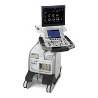
GE Vivid E9 Service Manual (736 pages)
with XDclear
Brand:
GE
| Category:
Medical Equipment
| Size: 22.51 MB
Table of Contents
Table of Contents
19
CHAPTER 1 Introduction
21
Overview
21
Purpose of this Chapter
21
Contents in this Chapter
21
Chapter 1 Introduction
39
Service Manual Overview
40
Contents in this Manual
40
Overview
40
Typical Users of the Service Manual
41
VIVID E9 Models Covered by this Manual
42
VIVID E7 Models Covered by this Manual
42
Product Description
43
Important Conventions
44
Conventions Used in this Book
44
Standard Hazard Icons
45
Product Icons
46
Safety Considerations
50
Introduction
50
Human Safety
50
Mechanical Safety
53
Electrical Safety
55
Label, General Info - Xdclear
56
Label on Side Covers
61
Dangerous Procedure Warnings
62
Lockout/Tagout (LOTO) Requirements
63
Returning/Shipping Probes and Repair Parts
64
Electromagnetic Compatibility (EMC)
65
What Is EMC
65
Compliance
65
Electrostatic Discharge (ESD) Prevention
65
Customer Assistance
66
Chapter 3 System Setup
83
Setup Reminders
84
Receiving and Unpacking the Equipment
86
Preparing for Setup
98
Completing the Setup
99
Configuration
106
Connectivity Overview
119
Connectivity Setup
120
Options Setup
134
Setup Paperwork
135
Chapter 5 Components and Functions (Theory)
187
Insite Exc
189
VIVID E9 / VIVID E7 Overview
194
Top Console with LCD Monitor and Operator Panel
201
Main Console
208
Air Flow Control
209
Casters and Brakes
210
Front End Processor (FEP)
211
Back End Processor (BEP)
234
Power Distribution
251
Input and Output (I/O) Modules
262
Peripherals Overview
268
Product Manuals
270
Common Service Desktop Overview
271
Restart VIVID E9 / VIVID E7 after Diagnostics
273
Chapter 6 Service Adjustments
275
LCD Monitor Adjustments
276
Test the LCD Arm and LCD Monitor Range of Motion
278
Backlight Adjustment
279
Touch Screen Calibration
284
DC Offset Calibration (Front End Alignment)
285
Adjusting the XYZ Mechanism
286
Adjust Time-Out for DICOM Servers
291
Chapter 7 Diagnostics / Troubleshooting
293
FAQ - Frequently Asked Questions
294
Service Safety Considerations
294
Troubleshooting Tips
296
Network Connectivity Troubleshooting
300
Gathering Troubleshooting Data
302
Screen Captures
304
Motor Controller Test
305
Troubleshooting
307
Noise Troubleshooting
313
Chapter 8 Replacement Procedures
317
Warnings and Important Information
318
Definitions of Left, Right, Front and Back
322
Reloading the Software
323
Replacing Covers and Bumpers
340
Top Console Parts Replacement Overview
376
Replacing XYZ Parts
476
Main Console Parts Replacement
492
Casters and Brakes Replacement
510
Front End Processor (FEP) / Card Cage Parts Replacement
520
Back End Processor (BEP) Parts Replacement
545
Main Power Supply Replacement
589
I/O Modules Replacement
592
Peripherals Replacement
598
Chapter 9 Renewal Parts
611
Definitions of Left, Right, Front and Back
612
List of Abbreviations
613
VIVID E9 / VIVID E7 Models and Hardware/Software Compatibility
614
Software Overview
615
Covers and Bumpers
618
Top Console Parts
622
XYZ Parts
649
Main Console Parts
651
Casters (Wheels) Parts
653
Front End Processor (FEP) Card Rack Parts
655
Back End Processor (BEP) Spare Parts
657
Main Power Supply
659
I/O Modules
660
Peripherals for VIVID E9 / VIVID E7
661
Mains Power Cables - VIVID E9 / VIVID E7
665
Internal Cables - VIVID E9 / VIVID E7
666
Physio TX Parts
684
Options - VIVID E9 / VIVID E7
685
Product Manuals for VIVID E9 / VIVID E7
687
Why Do Maintenance
696
Maintenance Task Schedule
697
Tools Required
699
System Maintenance
700
Electrical Safety Tests
708
When There's too Much Leakage Current
722
GE Vivid E9 Quick Reference Cards (80 pages)
Brand:
GE
| Category:
Medical Equipment
| Size: 2.99 MB
Advertisement
Advertisement
Related Products
GE Vivid e
GE Vivid E9 Series
GE VividE80
GE VividE90
GE VividE95
GE VIVID 3 N RFI
GE Vivid i
GE Vivid S5
GE VividS70
GE VividS60
GE Categories
Refrigerator
Ranges
Microwave Oven
Air Conditioner
Dishwasher
More GE Manuals
Login
Sign In
OR
Sign in with Facebook
Sign in with Google
Upload manual
Upload from disk
Upload from URL