Sign In
Upload
Manuals
Brands
GE Manuals
Medical Equipment
Optima CT680 Series
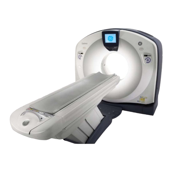
User Manuals: GE Optima CT680 Series CT Scanner
Manuals and User Guides for GE Optima CT680 Series CT Scanner. We have
1
GE Optima CT680 Series CT Scanner manual available for free PDF download: Installation Manual
GE Optima CT680 Series Installation Manual (206 pages)
Brand:
GE
| Category:
Medical Equipment
| Size: 9.7 MB
Table of Contents
Table of Contents
13
Optima Ct680 S
21
Publication Conventions
21
Safety & Hazard Information
21
Text and Character Representation
21
Graphical Representation
22
General Paragraph and Character Styles
23
Page Layout
23
Publication Conventions
23
Buttons, Switches and Keyboard Inputs (Hard & Soft Keys)
24
Computer Screen Output/Input Character Styles
24
Chapter 1 Position Subsystems
25
Section 1.0 Installer/Fe Notices
25
General Safety Guidelines
25
Shipping, Warehouse and Transportation Warning
25
International Shipments
25
On Site Warning
25
Service Actions
25
Introduction
26
Overview
26
Pre-Installation Template
26
Required Common Tools and Supplies
27
Section 3.0 Delivery Procedure
30
System Transportation - Temperature Extremes
30
Stored Systems
30
Construction Site Storage
30
Construction Site Installations
30
Construction Site with Completed Radiology Area
31
Full Construction Site with Limited Delivery Access
31
Construction Site Unpacking
31
Working with the Mover
32
Delivery Dolly Options
32
Equipment Delivery Route
32
Floor Protection
32
Removing Gantry Dollies and Covers
32
Damage in Transportation
32
A1 Breaker
33
Installation Conditions
33
Section 4.0 Layout the Floor Template
34
Optima Ct680 Series and
34
Time & Personnel
34
Tools and Test Equipment
34
Safety
34
Floor Preparation
34
Preparation
34
Flooring
34
Room Preparation
35
Procedure
35
Section 5.0 Install the Gantry
39
Time and Personnel
39
Tools and Test Equipment
39
Gantry Preparation
39
Access Greater than 28 in
39
Access Less than 28 in
39
Procedure
40
Section 6.0 Level the Gantry
43
Time and Personnel
43
Tools and Test Equipment
43
Procedure
43
Section 7.0 Gantry Bearing Gap Inspection
46
Time and Personnel
46
Tools and Test Equipment
46
Preparation: Damage Indicators
46
Procedure
47
Finalization
48
Mechanical Installers
48
FE Service Action, if Required
48
FE Inspection Completion
49
Section 8.0 Install Gantry Alignment Laser and Bracket
50
Time and Personnel
50
Tools and Test Equipment
50
Procedure
50
Section 9.0 Table Installation (GT1700V)
54
Time and Personnel
54
Tools and Test Equipment
54
Procedures
54
Draw Table Reference Lines
54
Removing the Accessory Rail Strip
58
Install the Table Cradle Laser Alignment Plates
58
Level and Center the Table to the Gantry
59
Conditions
59
Specifications
59
Procedure
59
Tighten the Lock Rings
62
Section 10.0 Table Installation (Lite Table)
63
Time and Personnel
63
Optima Ct680 S
63
Tools and Test Equipment
63
Procedures
63
Draw Table Reference Lines
63
Cradle Center Procedure
65
Install the Table Cradle Laser Alignment Plates
66
Level and Center the Table to the Gantry
67
Conditions
67
Specifications
67
Procedure
68
Section 11.0 Drill the Anchor Holes
69
Notes to Mechanical Installers
69
Requirements
69
Drilling Procedure (for Gantry and GT1700V Table)
70
Drilling Procedure (for Lite Table)
73
Gantry & Table (GT1700V) Alternate Anchor Holes
75
Lite Table Redundant Anchor Holes
76
Install the Anchors (for Gantry and GT1700V Table)
77
Install the Anchors (for Lite Table)
79
Alignment Recheck
80
Removing Table Shipping Dollies
81
Time and Personnel
81
Tools and Test Equipment
81
Preparation
81
Procedure
81
Section 12.0 Rear Entry Cable Box
83
Rear Entry with Surface Floor Duct
84
Section 13.0 Install Table Footswitch Assembly (GT1700V)
85
Time and Personnel
85
Tools and Test Equipment
85
Procedure
85
Section 14.0 Install Table Footswitch Assembly (Lite Table)
89
Time and Personnel
89
Tools and Test Equipment
89
Procedure
89
Section 15.0 Remove Gantry Tilt Bracket
91
Time and Personnel
91
Tools and Test Equipment
91
Procedure
91
Section 16.0 Position the Power Distribution Unit
92
Time and Personnel
92
Tools and Test Equipment
92
Procedure
92
Section 17.0 Install Operator Console
96
Time and Personnel
96
Tools and Test Equipment
96
Procedures
96
Install SWS Table
96
Peripherals Placement
96
Section 18.0 Seismic Mounting
97
Time and Personnel
97
Procedures
97
Console
97
Power Distribution Unit
98
Chapter 2 Power, Ground & Interconnect Cables
99
Section 1.0 Introduction
99
Cable Storage
99
System Component Identification
100
Cable Color Identifiers
100
Section 2.0 System Interconnect Diagram
102
Section 3.0 Console Connections
103
GSCB, Keyboard & Mouse Installation
103
Connecting the Media Tower (5270510-20/-21/-22)
106
Connecting the LCD Monitor
107
Connect Scan Monitor and Image Monitor for EIZO LCD
107
Connect Scan Monitor and Image Monitor for HP LCD
108
LCD Video Monitor Setup
109
Host Computer Connections
110
Switch Hub Connections
112
AC Box Connections
113
Cable Arrangement
114
Section 4.0 Install Options
115
Install USB Barcode Reader
115
Install Optional Remote Monitor
115
Install Accessory I/F Hardware (IPC) Option
115
Install Respiratory Gating Option
115
Install Injector Option
115
Install Cardiac Gating IVY Monitor and Stand Option
115
Customer Accessories - Head Holders and Extender
116
UPS Installation
116
Flat Tabletop Used with Respiratory Gating
116
Smartstep Installation
116
Section 5.0 Gantry Cable Connections
117
Gantry Cable Connections
117
Cardiac Monitor Setup
120
Respiratory Monitor Setup (Version 1.7)
122
Section 6.0 Table Connections (GT1700V)
123
Section 7.0 Table Connections (Lite Table)
124
PDU Cable Connections & Configuration
125
Introduction to NGPDU
125
Panel - 380 - 480VAC Mains "TS1" Input Power Connection
126
Panel - Circuit Breakers
126
HVDC Connection
127
Connection
128
Gantry & Console Power Connections
128
PDU Control Cable
129
System Ground Connection
129
Warning Light & Door Interlock Connections
130
Warning Light Configuration & Connection
130
Door Interlock Connections
131
Section 9.0 System Ground Connections
132
Chapter 3 System Continuity & Ground Checks
133
Section 1.0 System Continuity (Mechanical Contractor)
133
Time and Personnel
133
Tools and Test Equipment
133
Procedure
133
Section 2.0 Site Ground Continuity Check
137
Section 3.0 Shim Installation
138
Time and Personnel
138
Tools and Test Equipment
138
Preparation
138
Procedure
139
Finalization
140
Chapter 4 System Covers: Installation & Alignment
143
Section 1.0 Process Overview
143
Gantry Front Cover Installation
144
Gantry Rear Cover Installation
144
Gantry Bore Cover Installation
144
Gantry Top Covers
145
Installation
145
Gantry Side Covers
145
Gantry Strap Installation
145
Scan Windows
147
Installation
147
Install Gantry Base Covers
148
Tools Required
148
Procedure
148
Footswitch Covers Installation (GT1700V)
149
Section 2.0 Install Console Covers
150
Time and Personnel
150
Tools and Test Equipment
150
Procedures
150
Console Side Covers
150
Console Top Cover
151
Console Front Cover
152
Section 3.0 Table Cover Installation (GT1700V)
153
Side Covers
153
Install Panels
153
Top Panel #1
153
Bottom Panel #1
153
Top Panel #2
154
Bottom Panel #2
154
Re-Install Side Panel
154
Section 4.0 Table Covers Installation (Lite Table)
155
Flapper Installation
155
Skirt Cover Installation
156
Bottom Cover Installation
157
Section 5.0 Install All Option Covers
158
Section 6.0 Electrical Power on & Ground Checks
158
Introduction and Flowchart
159
Electrical Power on & Ground Checks Process Overview
159
Required Tools
159
Initial PDU Configuration
159
Circuit Breakers
159
Relay Board
159
Power Switches
160
Hardware and Connection Check
160
Covers
160
Suite Emergency off Checks
161
Line Transformer Settings
161
Requirements
161
Line Input Conditions
161
System Power-Up
162
Install PDU Covers
165
Time and Personnel
165
Tools and Test Equipment
165
Procedure
165
Emergency Stop Check
165
Section 7.0 Mechanical Installation Completion Checklist
167
Appendix A Gantry Cover Removal and Dolly Setup
169
Section 1.0 Gantry Cover Removal
169
Time & Personnel
169
Tools and Test Equipment
169
Procedures
169
Gantry Scan Window
169
Side Cover Removal
170
Top Cover Removal
171
Gantry Front Cover
172
Bore Cover Removal
183
Gantry Rear Cover
186
Appendix B
189
Pictorial Representation of Required Tools
189
Appendix C Operating Table Installation and Adjustment
193
Smart Workspace Table Assembly and Adjustment
193
Appendix D Remote Monitor Option Console Wiring
197
Power down System
197
Remote Monitor Wiring Overview
197
Wiring Installation
197
Install 4-Way Splitter
198
Advertisement
Advertisement
Related Products
GE Optima CT670
GE CT ProSpeed Series
GE Optima CT520
GE auisys cs2
GE CARESCAPE PDM
GE CARESCAPE CS
GE LOGIQ C5 Premium
GE LOGIC C2 Series
GE PathSpeed CR SP1001
GE Corometrics 250 Series
GE Categories
Refrigerator
Ranges
Microwave Oven
Air Conditioner
Dishwasher
More GE Manuals
Login
Sign In
OR
Sign in with Facebook
Sign in with Google
Upload manual
Upload from disk
Upload from URL