Sign In
Upload
Manuals
Brands
GE Manuals
Protection Device
MI-869
GE MI-869 Manuals
Manuals and User Guides for GE MI-869. We have
1
GE MI-869 manual available for free PDF download: Instruction Manual
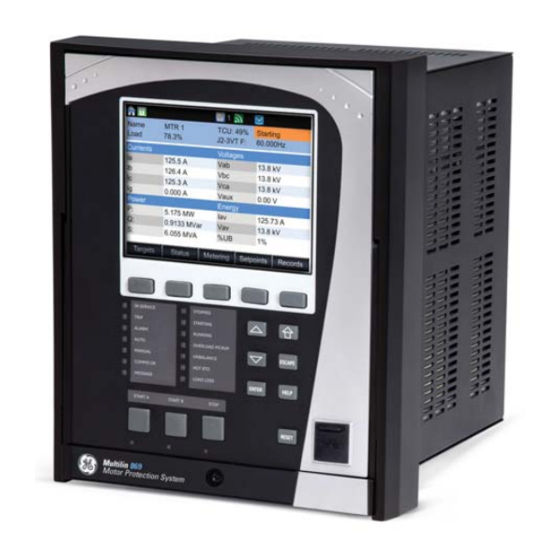
GE MI-869 Instruction Manual (552 pages)
Motor Protection System/Motor Protection, Control and Management
Brand:
GE
| Category:
Protection Device
| Size: 12.25 MB
Table of Contents
Table of Contents
3
INTRODUCTION Overview
11
Description of the 869 Motor Protection System
12
Security Overview
16
Order Codes
17
Specifications
19
Control
27
Monitoring
28
Recording
29
User-Programmable Elements
31
Metering
32
Inputs
34
Outputs
36
Power Supply
37
Communications
38
Physical
40
General Cautions and Warnings
41
Must-Read Information
43
Storage
44
INSTALLATION Mechanical Installation
45
Dimensions
46
Mounting
47
Standard Panel Mount
48
Draw-Out Unit Withdrawal and Insertion
49
Removable Power Supply
50
Removable Magnetic Module
51
Arc Flash Sensor
52
Electrical Installation
53
Terminal Identification
56
Wire Size
61
Ground and Sensitive Ground CT Inputs
62
Zero-Sequence CT Installation
63
Differential CT Inputs
64
Voltage Inputs
65
Control Power
66
Contact Inputs
67
Output Relays
68
Serial Communications
70
Irig-B
71
INTERFACES Front Control Panel Interface
74
Working with Graphical Display Pages
75
Single Line Diagram
78
LED Status Indicators
79
Home Screen Icons
80
Relay Messages
81
Self-Test Errors
82
Out of Service
86
Software Interface
87
Installing the Enervista 8 Series Setup Software
88
Upgrading the Software
90
Configuring Ethernet Communications
92
Connecting to the Relay
93
Working with Setpoints & Setpoints Files
94
File Support
96
Downloading & Saving Setpoints Files
97
Creating a New Setpoints File
98
Printing Setpoints
99
Loading Setpoints from a File
100
Uninstalling Files and Clearing Data
101
Upgrading Relay Firmware
104
Advanced Enervista 8 Series Setup Software Features
107
Transient Recorder (Waveform Capture)
108
Protection Summary
112
Offline Settings File Conversion
114
Convert 369 Files
115
Results Window
116
SETPOINTS Setpoints Main Menu
119
Setpoints Entry Methods
120
Common Setpoints
121
Logic Diagrams
122
Setpoints Text Abbreviations
123
Device
124
Custom Configuration
125
Real-Time Clock
127
Clock
129
SNTP Protocol
130
Security
131
Basic Security
132
Cybersentry
134
Communications
141
Rs485
146
Ethernet Ports
149
Routing
151
DNP Protocol
154
DNP / IEC104 Point Lists
155
Iec 60870-5-104
158
Iec 60870-5-103
159
Iec 61850
160
Remote Modbus Device
162
Transient Recorder
164
Data Logger
166
Fault Reports
168
Event Data
170
Programmable Pushbuttons
173
Front Panel
177
Default Screens
178
Installation
179
System
180
Current Sensing
181
Voltage Sensing
182
Power System
183
Motor
184
Variable Frequency Drives
189
Preset Values
194
Switching Device
195
Flexcurves
198
Inputs
200
Virtual Inputs
203
Analog Inputs
205
Remote Inputs
210
Outputs
211
Output Relay 1 (F1) Trip
212
Output Relay 2 (F4) Programmed as Close
215
Auxiliary Output Relays
216
Output Relay 3 (F7) Start Inhibit
217
Virtual Outputs
218
Analog Outputs
219
Protection
221
Motor Elements
223
Thermal Model
230
Current Unbalance
252
Mechanical Jam
257
Undercurrent
260
Loss of Excitation
263
Overload Alarm
269
Short Circuit
271
Ground Fault
274
Acceleration Time
278
Underpower
281
Speed Motor
284
Speed2 Acceleration
286
Speed2 Undecurrent
288
Current Elements
290
Percent of Load-To-Trip
298
Phase Instantaneous Overcurrent Protection
302
Phase Directional Overcurrent Protection
304
Neutral Time Overcurrent Protection
307
Neutral Instantaneous Overcurrent Protection
310
Neutral Directional Overcurrent Protection
313
Ground Time Overcurrent Protection
318
Ground Instantaneous Overcurrent Protection
320
Negative Sequence Instantaneous Overcurrent Protection
322
Voltage Elements
325
Undervoltage Curves
328
Phase Undervoltage Protection
329
Phase Overvoltage Protection
332
Auxiliary Undervoltage
335
Auxiliary Overvoltage Protection
338
Neutral Overvoltage Protection
341
Negative Sequence Overvoltage Protection
344
Volts Per Hertz
346
Impedance Elements
352
Power Elements
358
Reactive Power
364
Frequency Elements
367
Overfrequency
370
Frequency Rate of Change
373
Monitoring
377
Breaker Arcing Current
385
Breaker Health
388
Broken Rotor Bar
392
Stator Inter-Turn Fault
397
Functions
402
Demand
407
Pulsed Outputs
415
Digital Counters
418
Harmonic Detection
422
Speed
425
RTD Temperature
430
RTD Trouble
435
Loss of Communications
436
Control
438
Start Supervision
441
Maximum Starting Rate
444
Time between Starts
445
Restart Delay
447
Reduced Voltage Starting
448
Switching Device Control
452
Trip Bus
455
Breaker Failure
457
Setup
458
Initiate
460
Arc Flash Protection
462
VT Fuse Failure
464
Flexlogic
466
Timers
475
Non-Volatile Latches
476
Flexlogic Equation
477
Viewing Flexlogic Graphics
479
Flexelements
480
Testing
488
Setup
489
Pre-Fault
490
Post-Fault
491
Test Leds
492
STATUS Motor
493
Breakers
495
Last Trip Data
496
Output Relays
497
Virtual Outputs
498
Communications
499
Information
502
Hardware Versions
503
Device Status
504
Clock
505
METERING Summary
510
Motor
511
Speed
512
Stator Inter-Turn Fault
513
Impedance
514
Voltages
516
Frequency
517
Harmonics 1(Harmonics 2)
518
Harmonic Detection
519
Power
520
Energy
521
Power Factor
522
Power Demand
523
Rtds
524
Analog Inputs
525
RECORDS Events
527
Transient Records
528
Motor Start Records
529
Motor Start Statistics
530
Remote Modbus Device
533
Breakers
535
Remote Modbus Device
536
MAINTENANCE Environmental Health Report
539
Motor Health Report
541
General Maintenance
544
A.APPENDIX a Application Notes
545
Contactor Current Supervision
545
Warranty
547
Major Updates
548
Advertisement
Advertisement
Related Products
GE M60 UR Series
GE Multilin 3 Series
GE MLP1000
GE MLP2000
GE MLP3000
GE MLP4000
GE Multilin MIGII
GE Multilin UR Series
GE Multilin D30
GE MicroVersaTrip PM
GE Categories
Refrigerator
Ranges
Microwave Oven
Air Conditioner
Dishwasher
More GE Manuals
Login
Sign In
OR
Sign in with Facebook
Sign in with Google
Upload manual
Upload from disk
Upload from URL