Sign In
Upload
Manuals
Brands
GE HEALTHCARE Manuals
Medical Equipment
Logiq Book XP series
GE HEALTHCARE Logiq Book XP series Manuals
Manuals and User Guides for GE HEALTHCARE Logiq Book XP series. We have
1
GE HEALTHCARE Logiq Book XP series manual available for free PDF download: Basic Service Manual
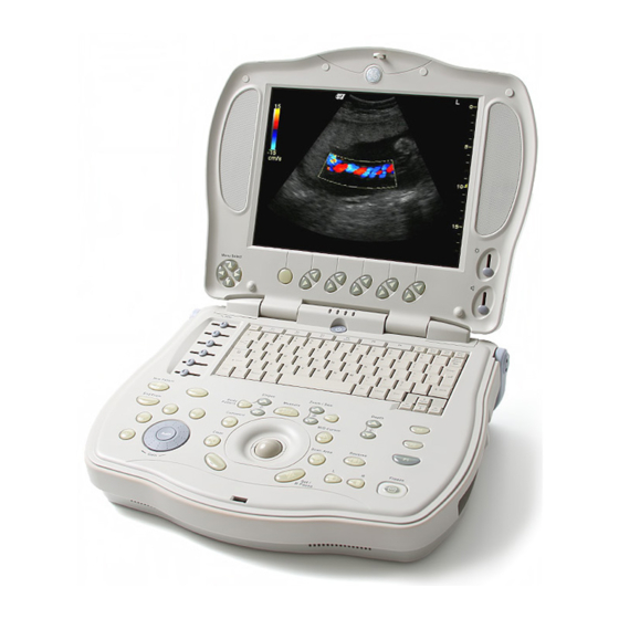
GE HEALTHCARE Logiq Book XP series Basic Service Manual (226 pages)
Ultrasound Machine
Brand:
GE HEALTHCARE
| Category:
Medical Equipment
| Size: 7 MB
Table of Contents
Part Number
12
Table of Contents
15
Overview
29
Chapter Contents
29
Purpose of Service Manual
29
Typical Users of the Basic Service Manual
30
Purpose of Operator Manual(S)
30
Important Conventions
31
Conventions Used in Book
31
Standard Hazard Icons
32
Product Icons
33
Chapter 1 Introduction
37
Human Safety
37
Mechanical Safety
37
Electrical Safety
38
Labels Locations
38
Battery Safety
39
Dangerous Procedure Warnings
40
Lockout/Tagout Requirements (for USA Only)
41
Returning/Shipping Probes and Repair Parts
42
Safety Considerations
37
EMC, EMI, and ESD
43
Electromagnetic Compatibility (EMC)
43
CE Compliance
43
Electrostatic Discharge (ESD) Prevention
43
Customer Assistance
44
Contact Information
44
System Manufacturer
45
Pre Installation
47
Overview
47
Purpose of this Chapter 2
47
Chapter Contents
47
General Console Requirements
48
Console Environmental Requirements
48
Lighting
48
Electrical Requirements
48
LOGIQ Book XP Series Power Requirements
48
Inrush Current
49
Site Circuit Breaker
49
Site Power Outlets
49
Unit Power Plug
49
Power Stability Requirements
49
EMI Limitations
50
Scan Probe Environmental Requirements
51
Facility Needs
52
Recommended Ultrasound Room Layout
52
Purchaser Responsibilities
52
Required Features
53
Desirable Features
53
Recommended and Alternate Ultrasound Room Layout
54
Networking Pre-Installation Requirements
55
Stand Alone System (Without Network Connection)
55
System Connected to Hospital's Network
55
Purpose of DICOM* Network Function
55
DICOM* Option Pre-Installation Requirements
55
Overview
57
Purpose of Chapter 3
57
Average Installation Time
57
Installation Warnings
58
Safety Reminders
59
Receiving and Unpacking the Equipment
60
Moving into Position
63
Packing the Equipment
63
Preparing for Installation
64
Verify Customer Order
64
Physical Inspection
64
System Voltage Settings
64
EMI Protection
64
Completing the Installation
65
Power on / Boot up
65
System Power on
65
Turn on the System
66
Power Off/ Shutdown
66
Back-End Processor Power down
66
System Shutdown
67
Transducer Connection
67
System Configuration
68
System Specifications
68
Physical Dimensions
68
Electrical Specifications
69
Approved Peripherals
69
Connecting Cables
70
Peripherals/Accessories Connector Panel
70
Rear Panel Connector
70
Connect Peripherals
74
Connect Peripherals
75
Available Probes
80
Software/Option Configuration
81
Connectivity Installation Worksheet
82
Loading the System Software
83
Loading the System Software with CD
84
Loading Base Image Software (for R2.2.1 or Lower)
84
Upgrading Application Software (for R2.2.1 or Lower)
86
Loading the System Software with DVD (for R2.2.2)
89
Loading the System Software with USB Memory Stick (for R2.2.2 or Above)
94
Functional Check-Out
99
Option Key Update
100
Probe Recognition Check
104
Peripheral Devices Check
104
Reinstall DICOM Devices
105
Revision
105
Paperwork
106
Product Locator Installation
106
User Manual(S)
106
Functional Checks
107
Overview
107
Purpose for Chapter 4
107
Required Equipment
107
General Procedure
108
Power On/Boot up
108
System Power on
108
Turn on the System
109
Power Off/ Shutdown
109
Back-End Processor Power down
109
System Shutdown
110
Archiving and Loading Presets
111
Archiving Presets to an CD-R Disk
111
Loading Presets from an CD-R Disk
111
Adjusting the Display Monitor
112
Brightness
112
Lockout/Tagout (LOTO) Requirements
112
System Features
113
Control Panel
113
LOGIQ Book XP Series Softmenu Key Tour
114
Monitor Display
115
B Mode Checks
116
Preparations
116
B Mode OP Panel Controls
117
B Mode Softmenu Key
118
M Mode Controls
119
Preparations
119
M Mode OP Panel Controls
120
M Mode Softmenu Key
121
Color Flow Mode Checks
122
Preparations
122
Color Flow Mode OP Panel Controls
123
Color Flow Mode Softemenu Key
124
Doppler Mode Checks
125
Preparations
125
Doppler Mode OP Panel Controls
126
Doppler Mode OP Panel Controls
127
Basic Measurements
128
Distance and Tissue Depth Measurements
128
Circumference/Area (Ellipse) Measurement
128
Worksheets
129
Ge Healthcare Direction
129
Irection Evision Logiq Book Xp Series Asic Ervice Anual
129
Report
129
Probe/Connectors Usage
129
Connecting a Probe
129
Activating the Probe
129
Deactivating the Probe
129
Disconnecting the Probe
129
Using Cine
130
Activating CINE
130
Quickly Move to Start/End Frame
130
Adjusting the CINE Loop Playback Speed
130
Moving through a CINE Loop Frame by Frame
130
Image Management (QG)
130
Backup and Restore Database, Preset Configurations and Images
131
Formatting Media
131
Backup System Presets and Configurations
132
Restore System Presets and Configurations
133
Archiving Images
134
Peripheral Checks
136
Software Configuration Checks
136
Components and Functions (Theory)
137
Overview
137
Block Diagrams and Theory
138
Block Diagram
138
General Information
139
Power Diagrams
140
Overview
140
AC Power
140
Air Flow Distribution
141
Fans
142
Common Service Platform
143
Introduction
143
Global Service User Interface (GSUI)
143
Internationalization
143
Service Login
143
Access / Security
143
The Usage for Security Cable
144
Service Home Page
145
Error Logs Tab (Not Available on LOGIQ Book XP Series Now)
146
Logs
147
Utilities
148
Search
148
Exit
149
Diagnostics
150
Diagnostics Execution
150
Diagnostic Reports
150
Image Quality
151
Calibration
151
Configuration
152
Utilities
152
Replacement
152
Service Adjustments
155
Overview
155
Purpose of this Chapter 6
155
Monitor Adjustments
156
Adjustments Procedures
156
Diagnostics/Troubleshooting
157
Overview
157
Purpose of Chapter 7
157
Gathering Trouble Data
158
Overview
158
Collect a Trouble Image with Logs
159
Screen Captures
160
Setting the P3 Key to Screen Capture
161
Capturing a Screen
162
Reset the P3 Key to Customer's Functionality
163
Global Service User Interface (GSUI)
164
Enter Global Service User Interface
164
Active Diagnostic Function
166
Reset Database
167
Clean Userdefs
169
Update FPGA
171
Control Frame
171
Button
171
Loop Count
171
Progress Indicator
172
Short Text Message
172
Background Color
172
Common Diagnostics
173
Utilities
173
Disruptive Mode
173
System Shutdown
173
PC Diagnostics (Non-Interactive Tests)
174
CPU Tests
174
Hard Drive Tests
174
Memory Tests
174
CD Drive Test
174
Video Test
174
USB Test
174
PC Diagnostics (Interactive Tests)
174
Keyboard Test
174
LCD Test
174
LOGIQ Book XP Series Diagnostic Descriptions
175
Troubleshooting
175
FRU Test
176
Mst
176
Dfp
177
Dtx
178
Dcnn
179
Logiq Book Xp Series Basic Service Manual
179
Replacement Procedures
181
Overview
181
Disassembly/Re-Assembly
181
Warning and Caution
181
Handle Assy (FRU No. 312)
183
Tools
184
Needed Manpower
184
Trackball Roller Cleaning
184
Preparations
184
Procedure
184
Renewal Parts
187
Overview
187
List of Abbreviations
187
Renewal Parts Lists
188
Equipment Models Covered in this Chapter
188
Operator Console Assy
189
Keyboard Assy
190
Bottom Assy
190
Isolation Cart Components
191
Isolation Cart Enhanced Version Components
194
Part Number
195
Accessories and Kits
196
Manuals
201
Probes
202
Care & Maintenance
203
Overview
203
Periodic Maintenance Inspections
203
Why Do Maintenance
204
Keeping Records
204
Quality Assurance
204
Maintenance Task Schedule
204
How Often Should Care & Maintenance Tasks be Performed
204
Tools Required
206
Special Tools, Supplies and Equipment
206
Specific Requirements for Care & Maintenance
206
System Maintenance
207
Preliminary Checks
207
Functional Checks (See also Chapter 4)
208
System Checks
208
Peripheral/Option Checks
209
Input Power
209
AC/DC Adapter Inspection
209
Cleaning
209
General Cleaning
209
Physical Inspection
210
Optional Diagnostic Checks
211
View the Logs
211
Probe Maintenance
211
Probe Related Checks
211
Basic Probe Care
211
Basic Probe Cleaning
211
Battery Performance Maintenance
212
Electrical Safety Tests
213
Safety Test Overview
213
GEMS Leakage Current Limits
214
Outlet Test - Wiring Arrangement
215
Chassis Leakage Current Test
216
Definition
216
Generic Procedure
216
Data Sheet for Enclosure Source Leakage Current
217
Ge Healthcare Direction
217
Probe Leakage Current Test
218
Definition
218
Generic Procedure
218
No Meter Probe Adapter Procedure
218
Data Sheet for Transducer Source Leakage Current
219
When There's too Much Leakage Current
220
Advertisement
Advertisement
Related Products
GE HEALTHCARE B20
GE HEALTHCARE B40
GE HEALTHCARE CARESCAPE Monitor B450
GE HEALTHCARE CARESCAPE Monitor B650
GE HEALTHCARE E-PRESTN
GE HEALTHCARE E-PRETN
GE HEALTHCARE E-PSM
GE HEALTHCARE E-PSMP
GE HEALTHCARE E-RESTN
GE HEALTHCARE Ettan DALTsix
GE HEALTHCARE Categories
Medical Equipment
Laboratory Equipment
Fitness Equipment
Measuring Instruments
Control Unit
More GE HEALTHCARE Manuals
Login
Sign In
OR
Sign in with Facebook
Sign in with Google
Upload manual
Upload from disk
Upload from URL