Sign In
Upload
Manuals
Brands
Garmin Manuals
Marine Radio
GTX 335
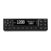
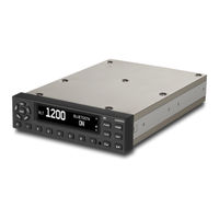
Garmin GTX 335 Manuals
Manuals and User Guides for Garmin GTX 335. We have
4
Garmin GTX 335 manuals available for free PDF download: Installation Manual, Maintenance Manual, Pilot's Manual
Garmin GTX 335 Installation Manual (199 pages)
Brand:
Garmin
| Category:
Marine Radio
| Size: 2.79 MB
Table of Contents
Table of Contents
6
1 System Overview
14
Equipment Description
14
Table 1-1 GTX 3X5 Units
14
ADS-B in
14
Definitions and Abbreviations
15
ADS-B Capabilities
16
Installation Approval for ADS-B Systems
16
FIS-B Capabilities
17
TIS System Capabilities
17
Interface Summary
18
Table
18
Table
19
General Specifications
20
Table 1-4 Physical Characteristics - Panel Mount Units
20
Table 1-5 Physical Characteristics - Remote Mount Units
21
Transponder Specifications
22
Table 1-6 Display Specifications
22
Table 1-7 GAE Specifications
22
UAT Receiver Specifications (GTX 345 Only)
23
1090 Mhz Receiver Specifications
23
GPS Specifications (Units with Internal GPS Only)
23
Table 1-9 UAT Receiver Specifications
23
Table 1-10 1090 Mhz Receiver Specifications
23
Table 1-11 GPS Receiver Specifications
23
Power Specifications
24
Certification
25
Table 1-13 TSO Compliance
25
Table 1-14 Applicable P/Ns
26
Table 1-15 TSO/ETSO Deviations
26
Table 1-16 Software Design Assurance Levels
27
Table 1-17 Complex Hardware Design Assurance Levels
27
Non-TSO Functions
27
Design Assurance Levels
27
License Requirements
28
Table 1-18 Equipment Authorization
28
Transmitter Grant of Equipment Authorization
28
Reference Documents
29
Table 1-19 Garmin Reference Documents
29
Table 1-20 Additional Reference Documents
29
2 Limitations
30
HSDB Packet Forwarding
30
ARINC 429 Data Concentrator Function
30
3 Installation Overview
31
Introduction
31
Unit Configurations
32
Table 3-1 GTX 3X5 Configurations
32
Accessories Supplied
33
Table 3-2 Accessories Supplied
33
Table
33
Optional Accessories
37
Table 3-3 Pressure Sensor Module
37
Table 3-4 GX000 System Rack
37
Table 3-5 GTX 3X5 Vertical Remote Mount Kits
37
Gae
37
GX000 System Rack
37
GTX 3X5 Vertical Remote Mount
37
GPS Antenna
38
Necessary Installation Materials and Accessories Not Supplied
39
Necessary Special Tools
39
Table 3-6 Recommended Crimp Tools
39
Transponder Antenna
40
Table 3-7 Acceptable UAT/1090 Antennas
40
GPS Antenna Requirements
41
Table 3-8 GNSS Receiver Antennas
41
Minimum Systems Configuration
42
Ads-B
42
Table 3-10 Compatible ADS-B Traffic/Fis-B Displays
42
Table 3-9 Minimum System Configuration
42
GTX Input Source Priority
43
Figure 3-1 Air Data Discrete Priority Order
43
Figure 3-2 Pressure Altitude Priority Order
44
Table 3-11 Air Data Select Source Priority
44
Table 3-12 Barometric Vertical Rate Source Priority
45
Table 3-13 Indicated Airspeed Source Priority
45
Table 3-14 True Airspeed Source Priority
45
Table 3-15 Barometric Pressure Setting Source Priority
46
Table 3-16 MCP/FCU Selected Altitude Source Priority
46
Table 3-17 Magnetic Heading Source Priority
47
Table 3-18 True Heading Source Priority
47
Table 3-19 Static Air Temperature Source Priority
47
Table 3-20 Total Air Temperature Source Priority
48
Table 3-21 Pressure Altitude Source Selection #1
48
Table 3-22 Pressure Altitude Source Priority Order #1
48
Table 3-23 Pressure Altitude Source Priority Order #12
49
Table 3-24 Baro-Corrected Altitude Source Selection #1
49
Table 3-25 Baro-Corrected Altitude Source Priority Order #1
49
Table 3-26 Baro-Corrected Altitude Source Priority Order #2
49
Table 3-27 AHRS Source Priority
50
Table 3-28 Airport Reference Points Source Priority
50
Table 3-29 Density Altitude Source Priority
50
Table 3-30 Height above Terrain Source Priority
50
Table 3-31 Radio Altitude Source Priority
51
Table 3-32 Selected Course and Joystick Waypoint Source Priority
51
Table 3-33 FMS Selected Altitude Priority
51
Table 3-34 Magnetic Variation Source Priority
51
ADS-B in Considerations
52
Table 3-35 EHS Roll Angle Source Priority
52
Table 3-36 Mach Source Priority
52
Table 3-37 Inertial Vertical Rate Source Priority
52
Bluetooth Considerations (GTX 345R Only)
53
Field Enablements
53
GPS/SBAS Parameters
53
Figure 3-3 Garmin Label on Remote Unit
53
Antenna Considerations
54
Transponder Antenna
54
GPS Antenna
55
Figure 3-4 GPS Locations of Antennas
56
Electrical Bonding
57
Cabling and Wiring
57
Electrical Bonding Considerations
57
Cooling Requirements and Considerations
57
4 Installation Procedure
58
Wire Harness Installation
58
Backshell Assembly Parts
59
Table 4-1 Backshell Assembly
59
Shielded Cable Preparation
60
Figure 4-1 Shielded Cable Preparation
61
Connector and Backshell Assembly
62
Figure 4-2 Shield Termination on Backshell Assembly
63
Figure 4-3 Connector and Backshell Assembly
64
Configuration Module Installation
65
Figure 4-4 Configuration Module Installation
66
Table 4-2 Configuration Module Kit, P/N 011-00979-03
66
Coax Cable Installation
67
Equipment Rack Installation
67
Panel Mount Units
67
Standard Remote Mount Units
68
Vertical Remote Mount Units
68
GX000 Integrated Flight Decks
68
GAE Installation
68
Figure 4-5 GAE Assembly
69
Panel and Standard Remote Mount Unit Installation and Removal
70
Vertical Remote Mount Unit Installation and Removal
71
5 Connector Pinout Information
72
Main Board Connector - J3251
73
Table 5-1 J3251 Connector
73
ADS-B Board Connector - J3252 (GTX 345 Only)
76
Table 5-2 J3252 Connector
76
Power
77
Table 5-3 Power Pins
77
Table 5-4 Power Configuration and Control Inputs
77
Table 5-5 Power Configuration and Power Control Functions
77
Power Configuration and Control Inputs
77
Lighting Bus
78
Altitude Inputs
78
Table 5-6 Lighting Bus Pins
78
Pressure Sensor Module
78
Discrete I/O
79
Table 5-7 Altitude Inputs
79
Table 5-8 Discrete Inputs and Outputs
79
Gray Code Altitude Input
79
Serial Data Interfaces
80
Table 5-9 RS-232 Inputs and Outputs
80
Table 5-10 ARINC 429 Inputs and Outputs
81
Table 5-11 Ethernet Inputs and Outputs
81
Table 5-12 RS-422 Outputs
81
Arinc 429
81
Hsdb
81
Suppression Bus
82
OAT Input
82
Audio Output
82
Time Mark
82
Table 5-13 External Suppression Bus Pin
82
Table 5-14 OAT Input and Output
82
Table 5-15 Audio Inputs and Outputs
82
Table 5-16 Time Mark Outputs
82
Configuration Module
83
USB Interface
83
Table 5-17 Configuration Module Inputs and Outputs
83
Table 5-18 USB Inputs and Outputs
83
6 Post Installation Configuration & Checkout
84
System Configuration Overview
84
Mounting, Wiring, and Power Checks
84
Configuration Mode and Settings
85
Audio Settings
86
Figure 6-1 Audio Group
86
Figure 6-2 Audio Page
86
Figure 6-3 Audio
87
Figure 6-4 Audio
87
Interfaces
88
Figure 6-5 Interface Group
88
Table 6-1 RS-232 Channel 1 through Channel 3 Selections
89
Figure 6-6 RS-232 Interface Page
90
Table 6-2 RS-232 Channel 4 Selections
90
Figure 6-7 RS-422 Output Page
91
Table 6-3 RS-422 Selections
91
Figure 6-8 A429 in Page
92
Table 6-4 ARINC 429 Inputs
92
Figure 6-9 A429 Output Page
93
Table 6-5 ARINC 429 Outputs
93
Table A-7 Transponder Control Format 1
93
Figure 6-10 HSDB Interface Page
94
Table 6-6 HSDB Formats
94
Figure 6-11 Discrete in Page
95
Table 6-7 Discrete Inputs
95
Figure 6-12 Discrete out Page
96
Table 6-8 Discrete Outputs
96
Figure 6-13 Unit Group
97
Figure 6-14 FIS-B Processing Page
97
Unit Settings
97
Figure 6-15 Altitude and Temperature Units Page
98
Figure 6-16 Installation and VFR ID Page
98
Figure 6-17 Altitude Alert Deviation and Restore Page
99
Figure 6-18 Flash Message Indicator Page
99
Figure 6-19 Bluetooth Page
99
Figure 6-20 EHS Page
99
Display
100
Figure 6-21 Display Group
100
Figure 6-22 Display Backlight and Minimum Level Page
101
Figure 6-23 Keypad Backlight and Minimum Level Page
101
Figure 6-24 Photocell Transition, Slope, and Offset Page
102
Figure 6-25 Lighting Bus Input Voltage Page
102
Figure 6-26 Default Backlight and Contrast Offset Page
103
Figure 6-27 Sensor Group
104
Sensors
104
Figure 6-28 Sensor Page
105
Figure 6-29 Altitude Source Page
105
Figure 6-30 Source, Integrity, and Offset Page
107
Figure 6-31 Internal Alt Encoder Page
107
Figure 6-32 Internal Alt Encoder Adjustment Page
107
Figure 6-33 Setting the Yaw Angle
108
Figure 6-34 Internal AHRS Orientation Page
108
Figure 6-35 Internal AHRS Calibration Page
109
Adsb
110
Figure 6-36 ADS-B Group
110
Figure 6-37 Aircraft Category and Max Airspeed Page
111
Figure 6-38 Aircraft Stall Method and Stall Speed Page
111
Figure 6-39 Aircraft Length and Width Page
112
Figure 6-40 1090ES out Control and UAT out Remote Control Page
112
Figure 6-41 1090ES in Capable and UAT in Capable Page
112
Figure 6-42 ADS-B in Processing Page
113
Figure 6-43 Aircraft Tail Number and Address Page
113
Figure 6-44 Allow Pilot to Edit Flight ID Page
113
Figure 6-45 Default Flight ID and Flight ID Prefix Page
114
Diagnostics
115
Figure 6-46 Diagnostics Group
115
Figure 6-47 Diagnostics Page
116
Ground Check - GPS Reception Check
116
Remote Unit Configuration
116
Ground Check - Transponder
117
Software Installation Procedure
117
7 Continued Airworthiness
118
Appendix A Data Formats
119
Air Data Input Format
119
ARINC 429 Input Formats
123
Table A-1 AHRS Inputs
123
Table A-2 ADC Inputs
123
Table A-3 ARINC 743A Inputs
124
Table A-4 EFIS Air Data
125
Table A-5 Flight Control
125
Table A-6 Heading
126
Table A-8 Radio Altitude
126
ARINC 429 Output Formats
127
Table A-9 Traffic Inputs
127
Table A-10 GPS Data Formats
127
Table A-11 Garmin Labels
128
Table A-12 TAS Output Labels
128
Table A-13 TIS-A Output Labels
129
Table A-14 Transponder Control Format 1 Labels
129
Table A-15 Traffic Labels
130
Appendix Bgtx 3X5 Mechanical Drawings
131
Figure B-1 GTX 3X5 GPS Panel Mount Assembly
132
Figure B-2 GTX 3X5 GPS Panel Mount Dimensions and Center of Gravity
133
Figure B-3 GTX 3X5R GPS Standard Remote Mount Assembly
134
Figure B-4 GTX 3X5R GPS Standard Remote Mount Dimensions and Center of Gravity
135
Figure B-5 GTX 3X5 Vertical Remote Mount
136
Figure B-6 GTX 3X5 Vertical Remote Mount Dimensions and Center of Gravity
137
Figure B-7 GTX 3X5R GPS G1000 Mount Rack Assembly
138
Figure B-8 GTX 3X5R GPS G1000 Mounting Rack Dimensions and Center of Gravity
139
Figure B-9 GTX 3X5 Panel Cutout Detail
140
Figure B-10 GTX 3X5 Connector and Vent Locations
141
Figure B-11 Optional Garmin Altitude Encoder
141
Appendix C Equipment Compatibility and Configuration
143
ADS-B in Displays
143
GPS Sources
144
Table C-2 GPS Source
144
Altitude Sources
145
Table C-3 Altitude Sources
145
Audio Panels
147
Radar Altimeters
147
Table C-4 Audio Panels
147
Table C-5 Radar Altimeters
147
Heading Reference Sources
148
Table C-6 Heading Reference Source
148
Traffic Sensors (GTX 345 Only
150
Table C-7 Traffic Sensors
150
Bluetooth
151
Table C-8 Bluetooth
151
Remote Control
152
Table C-9 Remote Control
152
TIS-A Display
153
Table C-10 TIS-A Displays
153
Appendix D Interconnect Drawings
154
Figure D-1 GTX 3X5 Power Configuration Typical Interconnect
156
Figure D-2 GTX 345 - G1000 Interconnect
158
Figure D-3 GTX 335 - G1000 Interconnect
160
Figure D-4 GTX 3X5 - GNS 480 (CNX80) Interconnect
161
Figure D-5 GTX 335 - GTN 6XX/7XX Typical Interconnect
162
Figure D-6 Single/Dual GTX 335 - Single GTN 6XX/7XX Interconnect
163
Figure D-7 GTX 345 - GTN 6XX/7XX Typical Interconnect
164
Figure D-8 GTX 345 - Single/Dual GTN 6XX/7XX Interconnect
166
Figure D-9 GTX 335/345 - GDL 88 Interconnect
167
Figure D-10 GTX 345 - Traffic Sensor Interconnect
169
Figure D-11 GTX 345 - Single and Dual 400W/500W Series
172
Figure D-12 GTX 3X5 - Audio Interconnect
173
Figure D-13 GTX 3X5 - Radio Altimeter Interconnect
174
Figure D-14 GTX 3X5 - Ahrs/Heading Source
175
Figure D-15 GTX 3X5 - Switches and OAT Probe Interconnect
176
Figure D-16 GTX 3X5 - Altitude Source Interconnect
177
Figure D-17 GTX 335 - GNS 400W/500W Series Interconnect
179
Figure D-18 GTX 345/345R - Flight Stream Interconnect
180
Figure D-19 GTX 345 - MX20/GMX 200 Interconnect
181
Figure D-20 GTX 335 - GDU 620 Interconnect
181
Appendix Ecs-Acns Compliance Matrix
182
Elementary Surveillance (ELS
182
Els
182
Enhanced Surveillance (EHS
188
Ads-B
190
Advertisement
Garmin GTX 335 Maintenance Manual (133 pages)
Brand:
Garmin
| Category:
Marine Radio
| Size: 12.27 MB
Table of Contents
Table of Contents
5
1 Introduction
10
Applicability
11
Publications
11
Revision and Distribution
11
Table 1-1 Reference Documentation
11
Reference
12
Terminology
12
Acronyms
12
2 System Description
13
Gtx 330/330D
14
Figure 2-1 GTX 330 or GTX 330D Interface Summary
15
Gtx 33/33D
16
Figure 2-2 GTX 33 or GTX 33D Interface Summary
17
Gtx 335/335R
18
Figure 2-3 GTX 335 or GTX 335R Interface Summary
19
Gtx 345/345R
20
Figure 2-4 GTX 345 or GTX 345R Interface Summary
21
GTX 335R/345R with Legacy G1000
22
Figure 2-5 GTX 335R or GTX 345R Interface Summary with Legacy G1000
22
Electrical Load Information
23
Table 2-1 GTX Electrical Load
23
3 Gtx Control and Operation
24
Figure 3-1 GTX 330/330D Front Panel
25
Gtx 330/330D
25
Figure 3-2 GTX 335/345 Front Panel
28
Gtx 335/345
28
Figure 3-3 GTN 7XX Transponder Control
31
Figure 3-4 GTN 6XX Transponder Control
31
GTX 33/33D and GTX 335R/345R
31
Figure 3-5 GNS 480 Transponder Control
32
GTX 335R/345R with Legacy G1000
32
Figure 3-6 G1000 Transponder Control
33
Figure 3-7 G1000 Transponder Control
34
Figure 3-8 USB a and USB B Connectors
35
GTX 3X5 Install Tool
35
Figure 3-9 GTX 3X5/3X5R State Page
36
State Page
36
Figure 3-10 GTX 3X5/3X5R Status Page
37
Status Page
37
Figure 3-11 GTX 3X5/3X5R Configuration Group
38
Configuration Group
38
Diagnostics Group
39
Figure 3-12 GTX 3X5/3X5R Diagnostics Group
40
Figure 3-13 GTX 3X5/3X5R Product Data Group
41
Product Data Group
41
Software Upload Group
41
Servicing Information
43
Maintenance Intervals
44
Table 4-1 Maintenance Intervals
44
Visual Inspection
45
Additional Instructions
47
Electrical Bonding Test
47
5 Troubleshooting
48
GTX General Troubleshooting
48
Figure 5-1 GTX (All Models) Transponder Troubleshooting
49
Figure 5-2 GTX 330/330D Transponder Failure/Fault Messages
50
GTX Failure Annunciations
50
Figure 5-3 GTX 33/33D Transponder Failure/Fault Messages
51
Figure 5-4 GTX 3X5 Transponder Alerts
52
Figure 5-6 Rear View, Connector P3301
57
GTX 33X Connector Pinout Information
57
Table 5-1 GTX 33X Pinout
57
Gtx 33X (J3301)
57
Table 5-2 GTX 33X Encoded Altitude Pin Assignments
59
Altitude Functions
59
Table 5-3 GTX 33/330 Discrete Outputs
60
Table 5-4 GTX 33/330 Discrete Inputs
60
Table 5-5 GTX 33/330 RS-232 Connections
60
Discrete Functions
60
Input/Output
60
Figure 5-7 GTX 33/330 ARINC 429 Connections
61
ARINC 429 Input/Output
61
Figure 5-8 Rear View, Connector J3251
62
GTX 3X5 Connector Pinout Information
62
Table 5-6 J3251 Pinout
62
Gtx 3X5 (J3251)
62
Figure 5-9 Rear View, Connector J3252
64
Table 5-7 J3252 Pinout
64
Gtx 345/345R (J3252)
64
Table 5-8 GTX 3X5/3X5R Encoded Altitude Pin Assignments
65
Altitude Functions
65
Table 5-9 GTX 3X5/3X5R Discrete Outputs
66
Discrete Functions
66
Table 5-10 GTX 3X5/3X5R Configurable Output Pins
67
Table 5-11 GTX 3X5/3X5R Discrete Inputs
67
Table 5-12 GTX 3X5/3X5R Configurable Input Pins
68
Table 5-13 GTX 3X5/3X5R RS-232 Connections
68
Input/Output
68
Table 5-14 GTX 3X5/3X5R ARINC 429 Connections
69
Table 5-16 GTX 345/345R HSDB Connections
69
ARINC 429 Input/Output
69
Out
69
HSDB Input/Output
69
6 Unit Removal and Reinstallation
70
Gtx 330/330D
70
Figure 6-1 GTX 330 Mounting Rack/Connector Assembly
71
Gtx 33/33D
72
Figure 6-2 GTX 33 Mounting Rack/Connector Assembly
72
Gtx 3X5
73
Figure 6-3 GTX 3X5 Connector Kits
73
Table 6-1 GTX 3X5 Connector Kit Hardware
73
Table 6-2 Standard/G1000 Mount Back Plate Hardware
73
Figure 6-4 GTX 3X5 Without GPS Back Plate Assembly (P/N 011-02976-00)
74
Figure 6-5 GTX 3X5 with GPS Back Plate Assembly (P/N 011-02976-01)
74
Figure 6-6 GTX 3X5 Vertical Mount Without GPS, Back Plate Assembly (P/N 011-02976-10)
75
Table 6-3 Vertical Mount Back Plate Hardware
75
Figure 6-7 GTX 3X5 Vertical Mount with GPS, Back Plate Assembly (P/N 011-02976-11)
76
Figure 6-8 GTX 3X5 Vertical Mount with TNC XPDR Back Plate Assembly (P/N 011-02976-12)
76
Figure 6-9 GTX 3X5 Mounting Rack/Connector Assembly
78
Figure 6-10 GTX 3X5R Standard Mounting Rack/Connector Assembly
80
Figure 6-11 GTX 3X5R G1000 Mounting Rack/Connector Assembly
80
Figure 6-12 GTX 3X5R Vertical Mounting Rack/Connector Assembly
82
Transponder Antenna
84
Figure 6-13 Garmin Altitude Encoder with Back Plate Assembly
84
Table 6-4 Garmin Altitude Encoder Kit - P/N 011-03080-00
84
7 Software
85
Software Check
85
Figure 7-1 GTX 330 Start-Up Screen
85
Figure 7-2 GTX 330 Product Data Page
86
Figure 7-3 GTX 3X5 Start-Up Screen
87
Figure 7-4 GTX 3X5 Product Data Page
87
Figure 7-5 GTN 6XX/7XX System Page
88
Figure 7-6 GX000 System Status Page
89
GTX 33/330 Software Update
90
Figure 7-7 Software Update Connection
90
GTX 3X5/3X5R Software Update
92
Figure 7-8 GTX 3X5 Install Tool Software Upload Page
93
8 System Configuration and Checkout
94
GTX 33/330 Configuration
94
Overview
94
System Checkout
94
GTX 33/330 Configuration
95
GTX 330/330D Configuration
95
GTX 33/33D Configuration (GTN 6XX/7XX)
95
GTX 33/33D Configuration (GNS 480)
95
GTX 3X5R Configuration (GTN 6XX/7XX, GNS 480, or G1000)
95
GTX 3X5 Configuration
95
GTX Airborne Test Mode
96
GTX 33/330 Airborne Mode (V8.02 or Higher)
96
Regulatory Test
97
GTX 3X5 Airborne Mode
97
ADS-B out Test
98
GTX 3X5 with TCAS System Test (GX000 Only)
99
Table 8-1 Ramp Test Pressure Altitude Check Scenario
99
9 System Return to Service Procedure
102
Maintenance Records
102
Appendix Ainstallation Specific Information
103
Appendix Bspecial Bonding Procedures
120
Considerations for Untreated or Bare Dissimilar Metals
120
Figure B-1 Electrical Bonding Preparation - Nut Plate
120
Figure B-2 Electrical Bonding Preparation - Bolt/Nut Joint
120
Figure B-3 Electrical Bond Preparation - Terminal Lug
120
Table B-1 Ground Plane Definitions and Ground Path Resistance Requirements
121
Preparation of Aluminum Surfaces
123
Composite Aircraft
123
Figure B-4 Fiberglass Insulation for Carbon Material
124
Figure B-5 Aluminum Tape Joint
125
Table B-2 Composite Airframe Bonding Hardware
125
Figure B-6 Aluminum Tape Ground Termination
126
Figure B-7 Remote GTX Aluminum Tape Installation
127
Tube and Fabric Aircraft
128
Table B-3 Tube and Fabric Airframe Bonding Hardware
129
Figure B-8 Electrical Bonding Using Conductive Clamp
130
Bonding Jumper
131
Figure B-9 Bonding Strap
132
Table B-4 Airframe Bonding Hardware
132
Garmin GTX 335 Installation Manual (67 pages)
TSO
Brand:
Garmin
| Category:
Marine Radio
| Size: 4.67 MB
Table of Contents
Table of Contents
5
1 System Overview
9
Scope
9
Equipment Description
9
GTX 3X5 Units
9
Definitions and Abbreviations
11
ADS-B Capabilities
12
TIS System Capabilities
12
Interface Summary
13
General Specifications
14
Physical Characteristics - Panel Mount Units
14
Physical Characteristics - Remote Mount Units
15
Transponder Specifications
16
UAT Receiver Specifications
16
Table 1-5 Display Specifications
16
1090 Mhz Receiver Specifications
17
GPS Specifications
17
Table 1-9 GNSS Receiver Specifications
17
GPS Antenna Requirements
18
Table 1-10 GNSS Receiver Antennas
18
Power Specifications
19
Table 1-11 Power Specifications
19
Certification
20
Table 1-12 TSO/ETSO Compliance
20
Table 1-13 TSO and ETSO Descriptions
21
Table 1-14 TSO/ETSO Deviations
21
Table 1-15 Software Design Assurance Levels
24
Table 1-16 Complex Hardware Design Assurance Levels
24
Operating Instructions
25
License Requirements
25
Reference Documents
25
2 Limitations
26
HSDB Packet Forwarding
26
3 Installation Overview
27
Introduction
27
Unit Configurations
27
Accessories Supplied
28
Optional Accessories
30
Installation Materials Required but Not Supplied
31
Installation Configurations
32
Special Tools Required
32
Table 3-2 Recommended Crimp Tools
32
Antenna Considerations
33
Electrical Bonding
35
Figure 3-1 Figure for Locations of Antennas
35
Cabling and Wiring
36
Shielding and Electrical Bonding Considerations
36
Cooling Requirements and Considerations
36
Mounting Requirements
36
4 Installation Procedure
37
Wiring Harness Installation
37
Backshell Assemblies
37
Coax Cable Installation
37
Connector Backshell Assembly
37
Equipment Mounting - Panel Mount Units
37
Equipment Mounting - Remote Mount Units
38
Antenna Installation
38
5 Connector Pinout Information
39
Main Board Connector - P3251
39
ADS-B Board Connector - P3252
41
Power
41
Lighting Bus
42
Antennas
42
Altitude Inputs
43
Discrete IO
44
Serial Data Interfaces
46
Suppression Bus
47
OAT Temperature Input
47
Audio Output
48
1PPS Interface
48
Configuration Module
48
USB Interface
49
6 Post Installation Configuration and Checkout
50
System Configuration Overview
50
Mounting, Wiring, and Power Checks
50
Connector Engagement Check
50
Configuration Setup
50
Remote Unit Configuration
52
Diagnostic Information
52
Ground Checks
52
Flight Checks
53
Database Check
53
Database Update Procedure
53
Software Loading Procedure
53
7 Continued Airworthiness
54
Appendixa Mechanical Drawings
55
Drawing List
55
Figure A-1 GTX 3X5 Panel Mount Assembly
55
Figure A-2 GTX 3X5 Panel Mount Dimensions and CG
55
Figure A-3 GTX 3X5 Horizontal Remote Mount Assembly
55
Figure A-4 GTX 3X5 Horizontal Remote Mount Dimensions and CG
55
Figure A-5 GTX 3X5 Vertical Remote Mount Assembly
55
Figure A-6 GTX 3X5 Vertical Remote Mount Dimensions and CG
55
Figure A-7 GTX 3X5 G1000 Mount Rack Assembly
55
Figure A-8 GTX 3X5 G1000 Mounting Rack Center of Gravity
55
Appendixb Interconnect Drawings
64
Figure B-1 GTX 345R G1000 Interconnect
64
Advertisement
Garmin GTX 335 Pilot's Manual (34 pages)
All-In-One ADS-B Transponder
Brand:
Garmin
| Category:
Marine Radio
| Size: 0.43 MB
Table of Contents
Table of Contents
9
1 GTX 3X5 Series Transponders
11
GTX 335 Transponder
11
GTX 345 Transponder
11
2 GTX 3X5 Controls
13
Power Control Keys
13
Mode Selection Keys
13
Squawk Code Keys
14
Figure 2-1 Squawk Code Entry Field
14
Table 2-1 Mode Section Key Functions
14
Table 2-2 Squawk Code Key Functions
14
Function Keys
15
Table 2-3 Function Keys
15
Remote Transponder Control
16
3 Display Functions and Settings
17
Transponder (XPDR)
17
Figure 3-1 Flight ID Edit Display Page
17
Figure 3-2 Flight ID Editable Display Page
17
Timers (TMR)
18
Altitude (ALT)
19
System (SYS)
20
Figure 3-3 Bluetooth Page
21
Figure 3-4 Bluetooth Pair Request Page
21
Figure 3-5 Paired Device List Page
21
Figure 3-6 Auto-Reconnect Page
21
Figure 3-7 Unpair Device? Page
22
Figure 3-8 (Selected) Bluetooth Device Name Page
22
4 ADS-B in (GTX 345 Only)
23
Traffic Alerting
23
TCAD/TAS/TCAS I GTX 345 Integration
24
5 FIS-B Weather and Flight Information
25
Table 5-1 FIS-B Weather Products
25
6 Connext Bluetooth
27
Table 6-1 GTX 345 Connext Features
27
7 Troubleshooting
29
Figure 7-2 ADS-B 1090 and Transponder Failed Screen
29
Advertisement
Related Products
Garmin GTX 330
Garmin GTX 335 Series
Garmin GTX 335R w/GPS
Garmin GTX 33
Garmin GTX 335 NV
Garmin GTX 335 w/GPS
Garmin GTX 335 w GPS
Garmin GTX 333
Garmin GTX-33ES
Garmin GTX 330ES
Garmin Categories
GPS
Watch
Car Navigation system
Avionics Display
Marine Equipment
More Garmin Manuals
Login
Sign In
OR
Sign in with Facebook
Sign in with Google
Upload manual
Upload from disk
Upload from URL