User Manuals: FUTABA T10J 10-Channel Transmitter
Manuals and User Guides for FUTABA T10J 10-Channel Transmitter. We have 4 FUTABA T10J 10-Channel Transmitter manuals available for free PDF download: Instruction Manual, Manual, Quick Start Manual

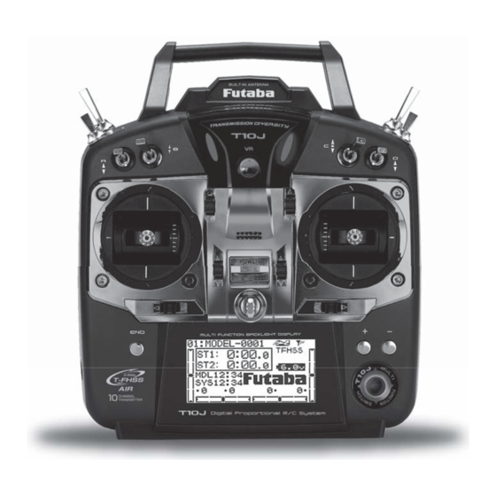
FUTABA T10J Instruction Manual (176 pages)
10-Channel Digital Proportional R/C System
Brand: FUTABA
|
Category: Remote Control
|
Size: 4.36 MB
Table of Contents
Advertisement
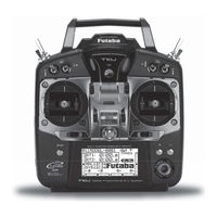
FUTABA T10J Manual (174 pages)
10 Channel Computer System
Brand: FUTABA
|
Category: Remote Control
|
Size: 36.9 MB
Table of Contents
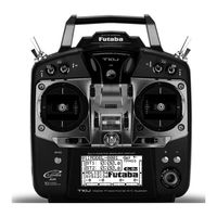
FUTABA T10J Instruction Manual (176 pages)
10-Channel digital proportional R/C system
Brand: FUTABA
|
Category: Remote Control
|
Size: 5.38 MB
Table of Contents
Advertisement

FUTABA T10J Quick Start Manual (3 pages)
Brand: FUTABA
|
Category: Remote Control
|
Size: 1.84 MB
Advertisement