
Fujitsu PRIMERGY TX2540 M1 Manuals
Manuals and User Guides for Fujitsu PRIMERGY TX2540 M1. We have 2 Fujitsu PRIMERGY TX2540 M1 manuals available for free PDF download: Upgrade And Maintenance Manual, Operating Manual
Fujitsu PRIMERGY TX2540 M1 Upgrade And Maintenance Manual (422 pages)
Table of Contents
-
-
Rack Model49
-
Tower Model56
-
Reassembling62
-
Rack Model63
-
Tower Model68
-
-
Processors94
-
-
Concluding Steps120
-
Concluding Steps122
-
Concluding Steps127
-
Concluding Steps129
-
Concluding Steps136
-
-
Mounting Order140
-
Concluding Steps148
-
Concluding Steps151
-
Concluding Steps153
-
Concluding Steps155
-
Concluding Steps164
-
Concluding Steps171
-
Concluding Steps173
-
Concluding Steps175
-
Concluding Steps180
-
Concluding Steps189
-
Concluding Steps193
-
Concluding Steps194
-
-
Concluding Steps201
-
Concluding Steps203
-
Concluding Steps204
-
8 Fans
205-
System Fans208
-
Concluding Steps208
-
Rear Fan209
-
Concluding Steps212
-
Concluding Steps214
-
Concluding Steps215
-
-
Concluding Steps235
-
Concluding Steps238
-
Concluding Steps240
-
Replacing TFM241
-
Concluding Steps242
-
Backup Units243
-
Installing a BBU244
-
Concluding Steps248
-
Concluding Steps253
-
Removing a BBU253
-
Removing the BBU254
-
Concluding Steps255
-
Removing an FBU256
-
Removing the FBU257
-
Concluding Steps258
-
Replacing a BBU259
-
Concluding Steps259
-
Replacing an FBU260
-
Concluding Steps261
-
10 Main Memory
263-
Concluding Steps268
-
Concluding Steps270
-
Concluding Steps271
-
11 Processors
273-
Concluding Steps279
-
Concluding Steps284
-
Concluding Steps286
-
Concluding Steps291
-
-
Backup Drives299
-
Concluding Steps305
-
Concluding Steps307
-
Concluding Steps308
-
-
Concluding Steps315
-
Concluding Steps320
-
Concluding Steps322
-
-
Concluding Steps327
-
Concluding Steps331
-
Concluding Steps332
-
-
Concluding Steps344
-
Concluding Steps346
-
Removing the UFM347
-
Removing the UFM348
-
Concluding Steps348
-
Concluding Steps351
-
Concluding Steps355
-
Removing the TPM356
-
Removing the TPM357
-
Concluding Steps359
-
Concluding Steps361
-
Concluding Steps363
-
Concluding Steps365
-
Concluding Steps376
-
16 Cabling
393 -
17 Appendix
405-
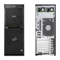
Server Front405
-
Server Rear406
-
Server Interior407
-
Onboard Settings419
-
Jumper Setting419
Advertisement

Advertisement