Sign In
Upload
Manuals
Brands
Fujitsu Manuals
Server
Primergy RX4770 M1
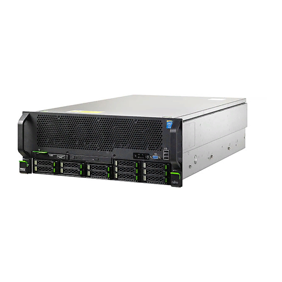
Fujitsu Primergy RX4770 M1 Manuals
Manuals and User Guides for Fujitsu Primergy RX4770 M1. We have
2
Fujitsu Primergy RX4770 M1 manuals available for free PDF download: Upgrade And Maintenance Manual
Fujitsu Primergy RX4770 M1 Upgrade And Maintenance Manual (332 pages)
Brand:
Fujitsu
| Category:
Server
| Size: 12.08 MB
Table of Contents
Copyright and Trademarks
2
Version History
6
Table of Contents
7
1 Introduction
19
Notational Conventions
20
2 Before You Start
21
Classification of Procedures
23
Customer Replaceable Units (CRU)
23
Upgrade and Repair Units (URU)
24
Field Replaceable Units (FRU)
25
Average Task Duration
25
Tools You Need at Hand
27
Documents You Need at Hand
29
3 Important Information
31
Safety Instructions
31
Energy Star
39
CE Conformity
39
FCC Class a Compliance Statement
40
Environmental Protection
41
4 Basic Hardware Procedures
43
Using Diagnostics Information
43
Locating the Defective Server
43
Determining the Error Class
44
Global Error Indicator
44
Customer Self Service (CSS) Indicator
44
Locating the Defective Component
45
Local Diagnostic Indicators on the Front
45
Local Diagnostic Indicators on the System Board
45
Shutting down the Server
46
Disconnecting Power Cords
46
Getting Access to the Component
48
Extending the Server out of the Rack
48
Removing the Server from the Rack
50
Opening the Server
52
Removing the Housing Cover
52
Reassembling
53
Closing the Server
53
Mounting the Housing Cover
53
Mounting the Server in the Rack
54
Seating the Server on the Rack Rails
54
Sliding the Server into the Rack
56
Connecting the Server to the Power Source
57
Switching on the Server
58
5 Basic Software Procedures
59
Starting the Maintenance Task
59
Suspending Bitlocker Functionality
59
Disabling SVOM Boot Watchdog Functionality
60
Viewing Boot Watchdog Settings
60
Configuring Boot Watchdog Settings
61
Removing Backup and Optical Disk Media
62
Verifying and Configuring the Backup Software Solution
63
Note on Server Maintenance in a Multipath I/O Environment
63
Switching on the ID Indicator
66
Completing the Maintenance Task
67
Updating or Recovering the System Board BIOS and Irmc
67
Updating or Recovering the System Board BIOS
67
Updating or Recovering the Irmc
67
Verifying System Information Backup / Restore
69
Updating RAID Controller Firmware
70
Enabling Option ROM Scan
71
Verifying and Configuring the Backup Software Solution
72
Resetting the Boot Retry Counter
73
Viewing the Boot Retry Counter
73
Enabling SVOM Boot Watchdog Functionality
74
Enabling Replaced Components in the System BIOS
75
Verifying the Memory Mode
76
Verifying the System Time Settings
77
Viewing and Clearing the System Event Log (SEL)
77
Viewing the SEL
77
Clearing the SEL
78
Updating the NIC Configuration File in a Linux Environment
79
Resuming Bitlocker Functionality
80
Performing a RAID Array Rebuild
81
Looking up Changed MAC / WWN Addresses
82
Looking up MAC Addresses
82
Looking up WWN Addresses
82
Using the Chassis ID Prom Tool
83
Configuring LAN Teaming
84
After Replacing / Upgrading LAN Controllers
85
After Replacing the System Board
85
Switching off the ID Indicator
85
Performing a Fan Test after Replacing a Defective Fan
86
6 Power Supply Units
89
Basic Information
89
Power Supply Unit Configurations
90
Assembly Rules
90
PSU Indicator
91
Installing Hot-Plug Power Supply Units
91
Preliminary Steps
91
Removing the Dummy Cover
92
Installing a Hot-Plug Power Supply Unit
93
Concluding Steps
93
Removing a Hot-Plug Power Supply Unit
94
Preliminary Steps
94
Removing a Hot-Plug Power Supply Unit
95
Installing a Dummy Cover
96
Concluding Steps
96
Replacing a Hot-Plug Power Supply Unit
97
Preliminary Steps
97
Removing the Defective Hot-Plug Power Supply Unit
97
Installing the New Hot-Plug Power Supply Unit
98
Concluding Steps
98
Replacing the Power Distribution Board
99
Preliminary Steps
99
Removing the Power Distribution Board
100
Installing the Power Distribution Board
102
Concluding Steps
105
7 Hard Disk Drives / Solid State Drives
107
Basic Procedures
108
Installing 2.5-Inch HDD / SSD / Pcie SSD Modules
110
Removing 2.5-Inch HDD / SSD / Pcie SSD Modules
112
Preliminary Steps
112
Removing a 2.5-Inch HDD / SSD / Pcie SSD Module
113
Concluding Steps
114
Replacing a 2.5-Inch HDD / SSD / Pcie SSD Module
114
Preliminary Steps
114
Removing a 2.5-Inch HDD / SSD / Pcie SSD Module
115
Installing a 2.5-Inch HDD / SSD / Pcie SSD Module
115
Concluding Steps
115
Removing a 2.5-Inch HDD / SSD Dummy Module
116
Replacing the SAS / SATA HDD / SSD Backplane
117
Preliminary Steps
117
Removing the HDD Backplane
118
Installing the HDD SAS Backplane
120
Concluding Steps
121
8 System Fans
123
Basic Information
123
Replacing the System Fan
124
Preliminary Steps
124
Removing a System Fan
125
Installing a System Fan
126
Concluding Steps
126
Replacing the Fan Backplane
127
Preliminary Steps
127
Removing the Fan Backplane
127
Installing the Fan Backplane
130
Concluding Steps
132
9 Expansion Cards and Backup Units
133
Basic Information
134
Expansion Cards and Backup Units
134
Handling Slot Brackets
138
Installing a Slot Bracket
138
Installing a Standard Slot Bracket
138
Installing a Slot Bracket to the Network Adapter D2755
140
Removing a Slot Bracket
142
Expansion Cards
142
Installing Expansion Cards
142
Preliminary Steps
142
Removing the Slot Bracket
143
Installing an Expansion Card
143
Concluding Steps
144
Removing Expansion Cards
145
Preliminary Steps
145
Removing an Expansion Card
146
Installing a PCI Slot Bracket
147
Concluding Steps
147
Replacing Expansion Cards
148
Preliminary Steps
148
Removing an Expansion Card
148
Installing an Expansion Card
149
Connecting Cables to the Expansion Card
149
Connecting a Battery Backup Unit to the Expansion Card
149
Concluding Steps
149
Replacing the SAS Riser
150
Removing the SAS Riser
150
Preliminary Steps
150
Removing the SAS Riser
151
Concluding Steps
151
Installing the SAS Riser
152
Preliminary Steps
152
Connecting a Backup Unit to the Expansion Card
153
Concluding Steps
153
BMC Riser
154
Replacing the BMC Riser
154
Preliminary Steps
154
Removing the BMC Riser
155
Installing the BMC Riser
156
Concluding Steps
156
Ê "Enabling SVOM Boot Watchdog Functionality
156
Ê "Resuming Bitlocker Functionality
156
Upgrading the BMC Riser
157
Basic Information
157
Preliminary Steps
157
Ê "Suspending Bitlocker Functionality
157
Ê "Disabling SVOM Boot Watchdog Functionality
157
Ê "Shutting down the Server
157
Installing the LAN Mezzanine Card
158
Concluding Steps
161
Replacing the LAN Mezzanine Card
161
Preliminary Steps
161
Removing the LAN Mezzanine Card
162
Installing the LAN Mezzanine Card
162
Concluding Steps
163
Irmc Microsd Card
163
Installing the Irmc Microsd Card
163
Preliminary Steps
163
Installing the Irmc Microsd Card
164
Concluding Steps
165
Removing the Irmc Microsd Card
165
Preliminary Steps
165
Removing the Irmc Microsd Card
166
Concluding Steps
166
Replacing the Irmc Microsd Card
167
Preliminary Steps
167
Concluding Steps
167
Pcie SW Card
168
Installing Pcie SW Cards
168
Preliminary Steps
168
Connecting Pcie Cables to the Drive Backplane (HSBP)
169
Cable Routing Pcie Cables
170
Installing the Pcie SW Card
171
Concluding Steps
172
Removing Pcie SW Cards
173
Preliminary Steps
173
Removing a Pcie SW Card
173
Concluding Steps
174
Replacing Pcie SW Cards
174
Preliminary Steps
174
Removing a Pcie SW Card
174
Installing a Pcie SW Card
175
Connecting Cables to the Pcie SW Card
175
Concluding Steps
175
Backup Units
176
Basic Information
176
Installing an FBU
177
Preliminary Steps
177
Installing a TFM to the SAS Riser (if Applicable)
177
Preparing the FBU
181
Connecting the FBU Cable to the FBU
182
Installing the FBU Holder Onto the Chassis
183
Connecting the FBU Cable to the SAS Riser (D3116)
185
Connecting the FBU Cable to the SAS Riser (D3216)
186
Concluding Steps
187
Removing an FBU
187
Preliminary Steps
187
Removing the FBU Holder from the Shoulder Screw Caps
188
Concluding Steps
189
Replacing an FBU
189
Preliminary Steps
189
Disconnecting the FBU Cable from the FBU
190
Removing the FBU from the Holder
191
Installing a New FBU
191
Concluding Steps
191
Handling SFP+ Transceiver Modules
192
Installing SFP+ Transceiver Modules
192
Removing an SFP+ Transceiver Module
197
Replacing SFP+ Transceiver Modules
199
10 Main Memory
201
Basic Information
202
Memory Sequence
204
Population Rules
204
DIMM Installation Recommendation
205
Installing Memory Modules
219
Preliminary Steps
219
Removing Memory Boards
220
Installing a Memory Module
222
Installing Memory Boards
223
Concluding Steps
224
Removing Memory Modules
225
Preliminary Steps
225
Removing a Memory Module
225
Concluding Steps
226
Replacing Memory Modules
227
Preliminary Steps
227
Removing the Defective Memory Module
227
Installing a New Memory Module
227
Concluding Steps
228
11 Processors
229
Basic Information
230
Supported Processors
230
Processor Locations
230
Installing Processors
231
Preliminary Steps
231
Installing a Processor
233
Concluding Steps
239
Removing Processors
240
Preliminary Steps
240
Removing a Processor
241
Concluding Steps
248
Upgrading or Replacing Processors
249
Preliminary Steps
249
Upgrading or Replacing a Processor
250
Concluding Steps
250
Handling Processor Heat Sinks
251
Preliminary Steps
251
Installing Processor Heat Sinks
252
Preparing the Heat Sink and Processor
252
Installing the Heat Sink
253
Removing Processor Heat Sinks
254
Replacing Processor Heat Sinks
255
Removing the Processor Heat Sink
255
Applying Thermal Paste
255
Installing the Processor Heat Sink
255
Concluding Steps
255
Applying Thermal Paste
256
12 Accessible Drives
259
Replacing the LSD Module
260
Preliminary Steps
260
Removing the LSD Module
260
Installing the LSD Module
262
Concluding Steps
262
Replacing the Optical Drive (ODD)
263
Preliminary Steps
263
Replace the Optical Drive
264
Concluding Steps
266
13 Front Panel and Chassis ID
267
Front Panel Module
267
Replacing the Front Panel Module
267
Preliminary Steps
267
Removing the Front Panel Module
268
Installing the Front Panel Module
269
Concluding Steps
269
Chassis ID
270
Replacing the Chassis ID
270
Preliminary Steps
270
Removing the Chassis ID
271
Installing the Chassis ID
272
Concluding Steps
272
14 System Board and Components
273
Basic Information
273
Replacing the CMOS Battery
274
Preliminary Steps
274
Removing the Battery
275
Installing the CMOS Battery
276
Concluding Steps
276
USB Flash Module (UFM)
277
Basic Information
277
Installing the UFM
277
Preliminary Steps
277
Installation the UFM
278
Concluding Steps
280
Software Configuration
281
Removing the UFM
281
Preliminary Steps
281
Removing the UFM
282
Concluding Steps
282
Replacing the UFM
283
Preliminary Steps
283
Removing the UFM
283
Installation of the New UFM
284
Concluding Steps
287
Software Configuration
287
Trusted Platform Module (TPM)
288
Installing the TPM
288
Preliminary Steps
288
Installing the TPM
289
Concluding Steps
291
Removing the TPM
292
Preliminary Steps
292
Removing the TPM
294
Concluding Steps
295
Replacing the TPM
296
Preliminary Steps
296
Removing the TPM
297
Re-Installing the TPM
297
Concluding Steps
297
Replacing the System Board
298
Preliminary Steps
300
Removing the Defective System Board
300
Installing the System Board
304
Installation of the System Board
304
Swapping Processors
307
Concluding Steps
308
15 Cables
311
List of Used Cables
311
Cabling Plan
313
16 Appendix
315
Mechanical Overview
315
Server Front
315
Server Rear
316
Server Interior
317
Configuration Tables
318
Hard Disk Drives / Solid State Drives Mounting Order
318
Memory Board Configuration Table
318
Connectors and Indicators
319
Connectors and Indicators on the System Board
319
Onboard Connectors
319
Onboard Indicators and Controls
321
Connectors and Indicators on the Rear Side
323
Rear Side Connectors
323
Rear Side Indicators and Controls
324
Connectors and Indicators on the Front Panel
327
Front Panel Connectors
327
Front Panel Indicators and Controls
328
Indicators on the Hot-Plug Hdd/Ssd/Pcie SSD
329
Onboard Settings
330
Minimum Startup Configuration
331
Advertisement
Fujitsu Primergy RX4770 M1 Upgrade And Maintenance Manual (328 pages)
Brand:
Fujitsu
| Category:
Server
| Size: 10.76 MB
Table of Contents
Copyright and Trademarks
2
Version History
6
Table of Contents
7
1 Introduction
17
Notational Conventions
18
2 Before You Start
19
Classification of Procedures
21
Customer Replaceable Units (CRU)
21
Upgrade and Repair Units (URU)
22
Field Replaceable Units (FRU)
23
Average Task Duration
23
Tools You Need at Hand
24
Documents You Need at Hand
27
3 Important Information
29
Safety Instructions
29
Energy Star
37
CE Conformity
37
FCC Class a Compliance Statement
38
Environmental Protection
39
4 Basic Hardware Procedures
41
Using Diagnostics Information
41
Locating the Defective Server
41
Determining the Error Class
42
Global Error Indicator
42
Customer Self Service (CSS) Indicator
42
Locating the Defective Component
43
Local Diagnostic Indicators on the Front
43
Local Diagnostic Indicators on the System Board
43
Shutting down the Server
44
Disconnecting Power Cords
44
Getting Access to the Component
46
Extending the Server out of the Rack
46
Removing the Server from the Rack
48
Opening the Server
50
Removing the Housing Cover
50
Reassembling
51
Closing the Server
51
Mounting the Housing Cover
51
Mounting the Server in the Rack
52
Seating the Server on the Rack Rails
52
Sliding the Server into the Rack
54
Connecting the Server to the Power Source
55
Switching on the Server
56
5 Basic Software Procedures
57
Starting the Maintenance Task
57
Disabling Bitlocker Functionality
57
Disabling SVOM Boot Watchdog Functionality
58
Viewing Boot Watchdog Settings
58
Configuring Boot Watchdog Settings
59
Removing Backup and Optical Disk Media
61
Verifying and Configuring the Backup Software Solution
61
Note on Server Maintenance in a Multipath I/O Environment
62
Switching on the ID Indicator
64
Completing the Maintenance Task
65
Updating or Recovering the System Board BIOS and Irmc
65
Updating or Recovering the System Board BIOS
65
Updating or Recovering the Irmc
66
Verifying System Information Backup / Restore
68
Updating RAID Controller Firmware
69
Enabling Option ROM Scan
70
Verifying and Configuring the Backup Software Solution
71
Resetting the Boot Retry Counter
72
Viewing the Boot Retry Counter
72
Enabling SVOM Boot Watchdog Functionality
74
Enabling Replaced Components in the System BIOS
74
Verifying the Memory Mode
75
Verifying the System Time Settings
76
Viewing and Clearing the System Event Log (SEL)
77
Viewing the SEL
77
Clearing the SEL
78
Updating the NIC Configuration File in a Linux Environment
78
Enabling Bitlocker Functionality
80
Performing a RAID Array Rebuild
81
Looking up Changed MAC / WWN Addresses
82
Looking up MAC Addresses
82
Looking up WWN Addresses
82
Using the Chassis ID Prom Tool
84
Configuring LAN Teaming
85
After Replacing / Upgrading LAN Controllers
85
After Replacing the System Board
85
Switching off the ID Indicator
86
Performing a Fan Test after Replacing a Defective Fan
86
6 Power Supply Units
89
Basic Information
89
Power Supply Unit Configurations
90
Assembly Rules
90
PSU Indicator
91
Installing Hot-Plug Power Supply Units
92
Preliminary Steps
92
Removing the Dummy Cover
92
Installing a Hot-Plug Power Supply Unit
93
Concluding Steps
93
Removing a Hot-Plug Power Supply Unit
94
Preliminary Steps
94
Removing a Hot-Plug Power Supply Unit
95
Installing a Dummy Cover
96
Concluding Steps
96
Replacing a Hot-Plug Power Supply Unit
97
Preliminary Steps
97
Removing the Defective Hot-Plug Power Supply Unit
97
Installing the New Hot-Plug Power Supply Unit
98
Concluding Steps
98
Replacing the Power Distribution Board
99
Preliminary Steps
99
Removing the Power Distribution Board
100
Installing the Power Distribution Board
102
Concluding Steps
105
7 Hard Disk Drives / Solid State Drives
107
Basic Procedures
108
Installing 2.5-Inch HDD / SSD Modules
110
Removing 2.5-Inch HDD / SSD Modules
112
Preliminary Steps
112
Removing a 2.5-Inch HDD / SSD Module
113
Concluding Steps
113
Replacing a 2.5-Inch HDD / SSD Module
114
Preliminary Steps
114
Removing a 2.5-Inch HDD / SSD Module
115
Installing a 2.5-Inch HDD / SSD Module
115
Concluding Steps
115
Removing a 2.5-Inch HDD / SSD Dummy Module
116
Replacing the SAS / SATA HDD / SSD Backplane
117
Preliminary Steps
117
Removing the HDD Backplane
118
Installing the HDD SAS Backplane
120
Concluding Steps
121
8 System Fans
123
Basic Information
123
Replacing the System Fan
124
Preliminary Steps
124
Removing a System Fan
125
Installing a System Fan
126
Concluding Steps
126
Replacing the Fan Backplane
127
Preliminary Steps
127
Removing the Fan Backplane
127
Installing the Fan Backplane
130
Concluding Steps
132
9 Expansion Cards and Backup Units
133
Basic Information
134
Handling Slot Brackets
137
Installing a Slot Bracket
137
Installing a Standard Slot Bracket
137
Installing a Slot Bracket to the Network Adapter D2755
139
Removing a Slot Bracket
141
Expansion Cards
141
Installing Expansion Cards
141
Preliminary Steps
141
Removing the Slot Bracket
142
Installing an Expansion Card
142
Concluding Steps
143
Removing Expansion Cards
144
Preliminary Steps
144
Removing an Expansion Card
145
Installing a PCI Slot Bracket
146
Concluding Steps
146
Replacing Expansion Cards
147
Preliminary Steps
147
Removing an Expansion Card
147
Installing an Expansion Card
148
Connecting Cables to the Expansion Card
148
Connecting a Battery Backup Unit to the Expansion Card
148
Concluding Steps
148
Replacing the SAS Riser
149
Removing the SAS Riser
149
Preliminary Steps
149
Removing the SAS Riser
150
Concluding Steps
150
Installing the SAS Riser
151
Preliminary Steps
151
Installing the SAS Riser
152
Connecting a Backup Unit to the Expansion Card
152
Concluding Steps
153
BMC Riser
154
Replacing the BMC Riser
154
Preliminary Steps
154
Removing the BMC Riser
155
Installing the BMC Riser
156
Concluding Steps
156
Upgrading the BMC Riser
157
Basic Information
157
Preliminary Steps
157
Ê "Disabling Bitlocker Functionality
157
Ê "Disabling SVOM Boot Watchdog Functionality
157
Ê "Shutting down the Server
157
Installing the LAN Mezzanine Card
158
Ê "Disconnecting Power Cords
158
Ê "Getting Access to the Component
158
Concluding Steps
161
Replacing the LAN Mezzanine Card
161
Preliminary Steps
161
Removing the LAN Mezzanine Card
162
Installing the LAN Mezzanine Card
162
Concluding Steps
163
Backup Units
164
Basic Information
164
Installing an FBU
165
Preliminary Steps
165
Installing a TFM to the SAS Riser (if Applicable)
165
Preparing the FBU
167
Connecting the FBU Cable to the FBU
169
Installing the FBU Holder Onto the Chassis
170
Connecting the FBU Cable to the SAS Riser (D3116)
172
Connecting the FBU Cable to the SAS Riser (D3216)
173
Concluding Steps
174
Removing an FBU
175
Preliminary Steps
175
Removing the FBU Holder from the Shoulder Screw Caps
176
Concluding Steps
177
Replacing an FBU
178
Preliminary Steps
178
Disconnecting the FBU Cable from the FBU
179
Removing the FBU from the Holder
180
Installing a New FBU
180
Concluding Steps
180
Handling SFP+ Transceiver Modules
182
Installing SFP+ Transceiver Modules
182
Removing an SFP+ Transceiver Module
187
Replacing SFP+ Transceiver Modules
189
10 Main Memory
191
Basic Information
192
Memory Sequence
194
Population Rules
194
DIMM Installation Recommendation
195
Installing Memory Modules
209
Preliminary Steps
209
Removing Memory Boards
210
Installing a Memory Module
213
Installing Memory Boards
214
Concluding Steps
215
Removing Memory Modules
216
Preliminary Steps
216
Removing a Memory Module
216
Concluding Steps
217
Replacing Memory Modules
218
Preliminary Steps
218
Removing the Defective Memory Module
218
Installing a New Memory Module
218
Concluding Steps
219
11 Processors
221
Basic Information
222
Supported Processors
222
Processor Locations
222
Installing Processors
223
Preliminary Steps
223
Installing a Processor
225
Concluding Steps
231
Removing Processors
232
Preliminary Steps
232
Removing a Processor
233
Concluding Steps
240
Upgrading or Replacing Processors
241
Preliminary Steps
241
Upgrading or Replacing a Processor
242
Concluding Steps
242
Handling Processor Heat Sinks
243
Preliminary Steps
243
Installing Processor Heat Sinks
244
Preparing the Heat Sink and Processor
244
Installing the Heat Sink
245
Removing Processor Heat Sinks
246
Replacing Processor Heat Sinks
247
Removing the Processor Heat Sink
247
Applying Thermal Paste
247
Installing the Processor Heat Sink
247
Concluding Steps
247
Applying Thermal Paste
248
12 Accessible Drives
251
Replacing the LSD Module
252
Preliminary Steps
252
Removing the Defective LSD Module
253
Installing the New LSD Module
255
Concluding Steps
255
Replacing the Optical Drive (ODD)
256
Preliminary Steps
256
Replace the Optical Drive
257
Concluding Steps
259
13 Front Panel and Chassis ID
261
Front Panel Module
262
Replacing the Front Panel Module
262
Preliminary Steps
262
Removing the Front Panel Module
263
Installing the Front Panel Module
264
Concluding Steps
264
Chassis ID
265
Replacing the Chassis ID
265
Preliminary Steps
265
Removing the Chassis ID
266
Installing the Chassis ID
267
Concluding Steps
267
14 System Board and Components
269
Basic Information
269
Replacing the CMOS Battery
270
Preliminary Steps
270
Removing the Battery
271
Installing the CMOS Battery
272
Concluding Steps
272
USB Flash Module (UFM)
273
Basic Information
273
Installing the UFM
273
Preliminary Steps
273
Installation the UFM
274
Concluding Steps
277
Software Configuration
278
Removing the UFM
278
Preliminary Steps
278
Removing the UFM
279
Concluding Steps
279
Replacing the UFM
280
Preliminary Steps
280
Removing the UFM
280
Installation of the New UFM
281
Concluding Steps
284
Software Configuration
284
Trusted Platform Module (TPM)
285
Installing the TPM
285
Preliminary Steps
285
Installing the TPM
286
Concluding Steps
288
Removing the TPM
290
Preliminary Steps
290
Removing the TPM
292
Concluding Steps
293
Replacing the TPM
294
Preliminary Steps
294
Removing the TPM
295
Re-Installing the TPM
295
Concluding Steps
295
Replacing the System Board
296
Preliminary Steps
298
Removing the Defective System Board
298
Installing the System Board
302
Installation of the System Board
302
Swapping Processors
306
Concluding Steps
306
15 Cables
309
List of Used Cables
310
Cabling Plan
311
16 Appendix
313
Mechanical Overview
313
Server Front
313
Server Rear
314
Server Interior
315
Configuration Tables
316
Hard Disk Drives / Solid State Drives Mounting Order
316
Memory Board Configuration Table
316
Connectors and Indicators
317
Connectors and Indicators on the System Board
317
Onboard Connectors
317
Onboard Indicators and Controls
319
Connectors and Indicators on the Rear Side
321
Rear Side Connectors
321
Rear Side Indicators and Controls
322
Connectors and Indicators on the Front Panel
325
Front Panel Connectors
325
Front Panel Indicators and Controls
326
Onboard Settings
327
Minimum Startup Configuration
328
Advertisement
Related Products
Fujitsu PRIMERGY RX4770 M2
Fujitsu PRIMERGY RX4770 M4
Fujitsu PRIMERGY RX4770 M6
Fujitsu PRIMERGY RX4770 M5
Fujitsu PRIMERGY RX200 S2
Fujitsu PRIMERGY RX350 S7
Fujitsu PRIMERGY RX2560 M2
Fujitsu PRIMERGY RX2560 M1
Fujitsu PRIMERGY RX2530 M4
Fujitsu PRIMERGY RX2540 M2
Fujitsu Categories
Air Conditioner
Laptop
Server
Scanner
Storage
More Fujitsu Manuals
Login
Sign In
OR
Sign in with Facebook
Sign in with Google
Upload manual
Upload from disk
Upload from URL