Sign In
Upload
Manuals
Brands
Fujitsu Manuals
Server
PRIMERGY RX350 S8
User Manuals: Fujitsu PRIMERGY RX350 S8 Rack Server
Manuals and User Guides for Fujitsu PRIMERGY RX350 S8 Rack Server. We have
1
Fujitsu PRIMERGY RX350 S8 Rack Server manual available for free PDF download: Upgrade And Maintenance Manual
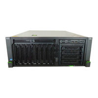
Fujitsu PRIMERGY RX350 S8 Upgrade And Maintenance Manual (792 pages)
Brand:
Fujitsu
| Category:
Server
| Size: 35.43 MB
Table of Contents
Copyright and Trademarks
2
Version History
5
Table of Contents
7
1 Introduction
31
2 Before You Start
33
Classification of Procedures
35
Customer Replaceable Units (CRU)
35
Upgrade and Repair Units (URU)
36
Field Replaceable Units (FRU)
37
Average Task Duration
38
Tools You Need at Hand
39
Documents You Need at Hand
41
Document Description
41
3 Important Information
45
Safety Instructions
45
CE Conformity
53
FCC Class a Compliance Statement
53
Environmental Protection
54
4 Basic Hardware Procedures
57
Using Diagnostics Information
57
Locating the Defective Server
57
Determining the Error Class
58
Global Error Indicator
59
Customer Self Service (CSS) Indicator
60
Locating the Defective Component
60
Local Diagnostic Indicators on the Front
60
Local Diagnostic Indicators on the System Board
61
Shutting down the Server
62
Disconnecting the Server from the Mains
63
Extending / Removing the Server from the Rack
64
Preliminary Steps
65
Extending the Server out of the Rack
65
Removing the Server from the Rack
66
Opening the Server
68
Rack Model
68
Removing the Top Cover
68
Removing the ID Card
69
Removing the Rack Mounting Frame
70
Tower Model
72
Unlocking the Server
72
Removing the Side Cover
74
Removing the ID Card
76
Removing Accessible Drive and HDD Bay Covers
77
Removing the Front Cover
80
Handling Fan Holders
81
Handling the System Air Duct
81
Removing the System Air Duct
81
Installing the System Air Duct
83
Handling the System Board Carrier
85
Removing the System Board Carrier
85
Installing the System Board Carrier
88
Handling Accessible Drive Bays
91
Opening the Accessible Drive Locking Bar
91
Tower Servers
91
Rack Servers
92
Closing the Accessible Drive Locking Bar
93
Tower Servers
93
Rack Servers
93
Accessible Drive Filler Covers
94
Removing Accessible Drive Filler Covers
94
Installing Accessible Drive Filler Covers
95
Accessible Drive Covers
96
Removing Accessible Drive Covers
96
Installing Accessible Drive Covers
97
Closing the Server
98
Rack Model
98
Installing the Rack Mounting Frame
98
Installing the ID Card
100
Mounting the Top Cover
101
Tower Model
103
Mounting the
103
Installing Accessible Drive and HDD Bay Covers
105
Installing the ID Card
107
Mounting the Side Cover
108
Locking the Server
110
Handling the Anti-Tilt Bracket
112
Installing the Anti-Tilt Bracket
112
Removing the Anti-Tilt Bracket
114
Mounting the Server in the Rack
115
Seating the Server on the Rack Rails
115
Sliding the Server into the Rack
117
Connecting the Server to the Mains
118
Securing Power Cords
118
Mounting a PSU Cable Bracket
118
Securing a Power Cord in the PSU Cable Bracket
121
Switching on the Server
123
Concluding Software Tasks
124
5 Basic Software Procedures
125
Starting the Maintenance Task
125
Suspending Bitlocker Functionality
125
Disabling SVOM Boot Watchdog Functionality
127
Viewing Boot Watchdog Settings
127
Configuring Boot Watchdog Settings
128
Removing Backup and Optical Disk Media
129
Verifying and Configuring the Backup Software Solution
129
Note on Server Maintenance in a Multipath I/O Environment
130
Switching on the ID Indicator
133
Completing the Maintenance Task
134
Updating or Recovering the System Board BIOS and Irmc
134
Updating or Recovering the System Board BIOS
134
Updating or Recovering the Irmc
134
Verifying System Information Backup / Restore
136
Updating RAID Controller Firmware
137
Enabling Option ROM Scan
138
Verifying and Configuring the Backup Software Solution
139
Resetting the Boot Retry Counter
140
Viewing the Boot Retry Counter
140
Resetting the Error Status after Replacing Memory Modules or Processors
142
Memory Modules
142
Processors
143
Performing a Fan Test after Replacing a Defective Fan
145
Enabling SVOM Boot Watchdog Functionality
146
Enabling Replaced Components in the System BIOS
147
Verifying the Memory Mode
147
Verifying the System Time Settings
148
Viewing and Clearing the System Event Log (SEL)
149
Viewing the SEL
149
Clearing the SEL
150
Updating the NIC Configuration File in a Linux Environment
150
Resuming Bitlocker Functionality
152
Performing a RAID Array Rebuild
153
Looking up Changed MAC / WWN Addresses
153
Looking up MAC Addresses
154
Looking up WWN Addresses
154
Using the Chassis ID Prom Tool
155
Configuring LAN Teaming
156
After Replacing / Upgrading LAN Controllers
157
After Replacing the System Board
157
Switching off the ID Indicator
158
Specifying the Chassis Model
158
6 Power Supply
161
Basic Information
162
PSU Installation Sequence
164
Assembly Rules
165
PSU Indicator
165
Installing PSU Modules
166
Removing the PSU Dummy Module
166
Installing a PSU Module
168
Concluding Steps
169
Removing PSU Modules
170
Preliminary Steps
170
Removing a PSU Module
171
Installing a PSU Dummy Module
172
Replacing PSU Modules
173
Preliminary Steps
174
Removing the Defective PSU Module
174
Installing the New PSU Module
174
Concluding Steps
174
Replacing the Power Backplane
175
Preliminary Steps
175
Removing the Power Backplane
176
Installing the Power Backplane
178
Concluding Steps
181
7 Hard Disk Drives / Solid State Drives
183
Basic Information
184
Inch HDD / SSD Configurations
185
Inch HDD / SSD Backplane Overview
185
SAS 3.0 HDD / SSD Backplane Cabling
186
8X 2.5-Inch Hdds / Ssds (2 SAS Backplanes)
189
Mounting Order for 2.5-Inch Hdds / Ssds
189
8X 2.5-Inch HDD / SSD SAS Backplane Cabling
189
HDD / SSD Naming Scheme
191
16X 2.5-Inch Hdds (4 SAS Backplanes)
192
Mounting Order for 2.5-Inch SAS 2.0 Hdds / Ssds
192
Mounting Order for 2.5-Inch SAS 2.0 / SAS 3.0 Hdds / Ssds
192
16X 2.5-Inch HDD / SSD SAS Backplane Cabling
193
HDD / SSD Naming Scheme
196
24X 2.5-Inch Hdds / Ssds (6 SAS Backplanes)
198
Mounting Order for 2.5-Inch SAS 2.0 Hdds / Ssds
198
Mounting Order for 2.5-Inch SAS 2.0 / SAS 3.0 Hdds / Ssds
199
24X 2.5-Inch HDD / SSD SAS Backplane Cabling
200
HDD / SSD Naming Scheme
204
Installing 2.5-Inch HDD / SSD Modules
207
Preliminary Steps
207
Removing a 2.5-Inch HDD / SSD Dummy Module
207
Installing a 2.5-Inch HDD / SSD Module
208
Concluding Steps
210
Removing 2.5-Inch HDD / SSD Modules
210
Preliminary Steps
210
Removing a 2.5-Inch HDD / SSD Module
211
Installing a 2.5-Inch HDD / SSD Dummy Module
213
Concluding Steps
213
Replacing a 2.5-Inch HDD / SSD Module
214
Preliminary Steps
214
Removing a 2.5-Inch HDD / SSD Module
215
Installing a 2.5-Inch HDD / SSD Module
215
Concluding Steps
215
Replacing a 2.5-Inch HDD SAS Backplane
215
Preliminary Steps
215
Removing the 2.5-Inch HDD Bay Top Cover
216
Removing a 2.5-Inch HDD Drive Cage
219
Replacing a 2.5-Inch HDD / SSD SAS Backplane
220
Mounting the Second 2.5-Inch HDD Drive Cage
224
Mounting the 2.5-Inch HDD Bay Top Cover
226
Concluding Steps
228
Upgrading to 16X 2.5-Inch HDD / SSD Configurations
229
Preliminary Steps
229
Removing the 8X 2.5-Inch HDD Front Panel
230
Removing the 2.5-Inch HDD Bay Top Cover
231
Mounting the Second 2.5-Inch HDD Drive Cage
234
Mounting the 2.5-Inch HDD Bay Top Cover
236
Installing the 16X 2.5-Inch HDD Front Panel
238
Cabling the SAS Backplanes
240
Concluding Steps
240
Inch HDD Configurations
241
Inch HDD Backplane Overview
241
4X 3.5-Inch Hdds (1 SAS Backplane)
242
Mounting Order for 3.5-Inch Hdds
242
4X 3.5-Inch HDD SAS Backplane Cabling
243
HDD Naming Scheme
243
8X 3.5-Inch Hdds (2 SAS Backplanes)
244
Mounting Order for 3.5-Inch Hdds
244
8X 3.5-Inch HDD SAS Backplane Cabling
245
HDD Naming Scheme
246
10X 3.5-Inch Hdds (3 SAS Backplanes)
247
Mounting Order for 3.5-Inch Hdds
247
10X 3.5-Inch HDD SAS Backplane Cabling
247
HDD Naming Scheme
249
12X 3.5-Inch Hdds (3 SAS Backplanes)
250
Mounting Order for 3.5-Inch Hdds
250
12X 3.5-Inch HDD SAS Backplane Cabling
251
HDD Naming Scheme
253
Installing 3.5-Inch HDD Modules
254
Preliminary Steps
254
Removing a 3.5-Inch HDD Dummy Module
255
Installing a 3.5-Inch HDD Module
256
Concluding Steps
257
Removing 3.5-Inch HDD Modules
258
Preliminary Steps
258
Removing a 3.5-Inch HDD Module
259
Installing a 3.5-Inch HDD Dummy Module
261
Concluding Steps
261
Replacing a 3.5-Inch HDD Module
262
Preliminary Steps
262
Removing a 3.5-Inch HDD Module
263
Installing a 3.5-Inch HDD Module
263
Concluding Steps
263
Replacing a 3.5-Inch HDD SAS Backplane
263
Preliminary Steps
263
Removing the 3.5-Inch HDD Bay Top Cover
264
Removing the Defective 3.5-Inch HDD SAS Backplane
267
Mounting the New 3.5-Inch HDD Backplane
268
Mounting the 3.5-Inch HDD Bay Top Cover
270
Concluding Steps
272
Upgrading to 8X 3.5-Inch HDD Configurations
272
Preliminary Steps
272
Removing the 3.5-Inch HDD Bay Top Cover
273
TX300 S8 / RX350 S8 Upgrade and Maintenance Manual
273
Removing the 4X 3.5-Inch HDD Front Panel
276
Mounting the Second 3.5-Inch HDD Backplane
277
Installing the 8X 3.5-Inch HDD Front Panel
279
Mounting the 3.5-Inch HDD Bay Top Cover
281
Cabling the SAS Backplanes
283
Concluding Steps
283
HDD Extension Boxes
284
HDD Extension Box Overview
284
8X 2.5-Inch HDD Extension Box
284
2X 3.5-Inch HDD Extension Box
285
4X 3.5-Inch HDD Extension Box
286
Installing the 2X 3.5-Inch HDD Extension Box
287
Preliminary Steps
287
Removing Accessible Drive Dummy Covers
287
Installing the Slimline ODD and LSD Module into the HDD Extension Box
287
Installing the 2X 3.5-Inch HDD Extension Box
288
Cabling the 2X 3.5-Inch HDD Extension Box
289
Installing HDD Modules into the 2X 3.5-Inch HDD Extension Box
290
Concluding Steps
290
Removing the 2X 3.5-Inch HDD Extension Box
291
Preliminary Steps
291
Installing Accessible Drive Dummy Covers
292
Concluding Steps
293
Replacing the 2X 3.5-Inch HDD Extension Box
293
Preliminary Steps
293
Removing the 2X 3.5-Inch HDD Extension Box
294
Removing the Slimline ODD and LSD Module from the Defective HDD Extension Box
294
Installing the Slimline ODD and LSD Module into the New HDD Extension Box
294
Installing the 2X 3.5-Inch HDD Extension Box
294
Concluding Steps
294
Installing the 4X 3.5-Inch HDD Extension Box
295
Installing the 4X 3.5-Inch HDD Extension Box
296
Cabling the 4X 3.5-Inch HDD Extension Box
297
Installing HDD Modules into the 4X 3.5-Inch HDD Extension Box
298
Removing the 4X 3.5-Inch HDD Extension Box
299
Installing Accessible Drive Dummy Covers
300
Removing the 4X 3.5-Inch HDD Extension Box
301
Installing the 8X 2.5-Inch HDD Extension Box
302
Installing the 8X 2.5-Inch HDD Extension Box
303
Cabling the 8X 2.5-Inch HDD Extension Box
304
Installing HDD Modules into the 8X 2.5-Inch HDD Extension Box
305
Removing the 8X 2.5-Inch HDD Extension Box
306
Installing Accessible Drive Dummy Covers
307
Concluding Steps
308
Sas Expander Board
309
Installing the Sas Expander Board
309
Preliminary Steps
310
Installing the SAS Expander Board
312
Concluding Steps
314
Removing the Sas Expander Board
315
Removing the SAS Expander Board
316
Concluding Steps
317
Replacing the Sas Expander Board
318
Concluding Steps
319
Basic Information
322
System Fans
324
Removing System Fan Modules
325
Installing System Fan Modules
327
Concluding Steps
329
Removing the System Fan Holder
330
Installing the System Fan Holder
331
Rear Fans
332
Installing a Rear Fan Module
333
Concluding Steps
335
Removing a Rear Fan Module
336
Concluding Steps
338
Replacing Rear Fan Modules
339
Replacing the Rear Fan Holder
340
Installing the Rear Fan Holder
342
Concluding Steps
343
Expansion Cards and Backup Units
345
Basic Information
346
Installing Expansion Cards
349
Preparing the Expansion Card
350
Removing PCI Slot Bracket
353
Installing an Expansion Card
354
Connecting Cables to the Expansion Card
356
Standard Expansion Cards
349
Removing Expansion Cards
357
Removing an Expansion Card
358
Installing a PCI Slot Bracket
360
Replacing Expansion Cards
361
Removing an Expansion Card
362
Connecting Cables to the Expansion Card
363
Installing the Modular Lan Controller
364
Preliminary Steps
365
Removing PCI Slot Bracket
368
Installing the Modular LAN Controller
369
Concluding Steps
371
Concluding Software Tasks
372
Removing the Modular Lan Controller
373
Removing the Modular LAN Controller
374
Installing a PCI Slot Bracket
377
Replacing the Modular Lan Controller
378
Removing the Modular LAN Controller
379
Concluding Steps
380
GPGPU / Coprocessor Cards in PCI Slots 6 and 8
381
GPGPU / Coprocessor Card Overview
382
Preliminary Software Tasks
383
Connecting GPGPU / Coprocessor Card Power Cables to the Power Backplane
384
Removing PCI Slot Brackets
388
Preparing the GPGPU / Coprocessor Card Mounting Bracket
390
Installing the GPGPU / Coprocessor Card Mounting Bracket
392
Installing a GPGPU or Coprocessor Card
395
Cabling the GPGPU / Coprocessor Card
402
Installing the GPGPU Air Duct
408
Installing the System Air Duct
418
Installing Perforated Drive Cover Modules
422
Concluding Steps
423
Replacing a GPGPU / Coprocessor Card
424
Installing the System Fan Holder
425
Installing the Sas Raid Controller
426
Preparing the SAS RAID Controller
427
Installing the SAS RAID Controller
428
Connecting Cables to the Expansion Card
429
Removing the Sas Raid Controller
430
Removing the SAS RAID Controller
431
Replacing the Sas Raid Controller
432
Removing the Defective SAS RAID Controller
433
Backup Units
434
Installing a Bbu
435
Preparing the BBU
436
Installing the BBU Holder into the Chassis
437
Concluding Steps
439
Installing an Fbu
440
Preliminary Steps
441
Preparing the FBU
447
Installing the FBU Holder into the Chassis
449
Concluding Steps
451
Removing a Bbu
452
Removing the BBU Holder from the Chassis
453
Removing an Fbu
454
Removing the FBU Holder from the Chassis
455
Replacing a Bbu
456
Removing the BBU from the BBU Holder
457
Installing a New BBU Module
459
Replacing an Fbu
460
Removing an FBU Module from the Chassis
461
Installing a New FBU Module
462
Concluding Steps
463
Removing the TFM Module
464
Installing the TFM Module
466
Main Memory
467
Memory Sequence
468
Independant Channel Mode
470
Mirrored Channel and Performance Modes
471
Rank Sparing Mode
472
Installing Memory Modules
476
Installing a Memory Module
477
Concluding Steps
478
Removing Memory Modules
479
Removing a Memory Module
480
Concluding Steps
481
Replacing Memory Modules
482
Installing a New Memory Module
483
Removing the Defective Memory Module
483
Supported Processors
485
Processor Locations
486
Installing Processors
486
Installing a Processor
487
Concluding Steps
495
Removing Processors
496
Removing a Processor
497
Concluding Steps
506
Upgrading or Replacing Processors
507
Upgrading or Replacing a Processor
508
Installing the Processor
513
Concluding Steps
516
Handling Processor Heat Sinks
518
Installing Processor Heat Sinks
519
Preparing the Heat Sink and Processor
520
Installing the Heat Sink
521
Removing Processor Heat Sinks
523
Replacing Processor Heat Sinks
525
Applying Thermal Paste
526
TX300 S8 / RX350 S8 Upgrade and Maintenance Manual
527
Accessible Drives
529
Basic Information
530
Installing Accessible Drives
533
Removing Accessible Drive Dummy Covers
533
Installing an Accessible Drive
534
Installing Mounting Brackets to RDX and DAT72 Backup Drives
535
Cabling the Accessible Drive
539
USB Backup Drive
541
SAS Backup Drives with Separate Power Supply
543
SAS Backup Drives with SAS Power Supply
545
Removing Accessible Drives
546
Removing an Accessible Drive
547
Installing Accessible Drive Dummy Covers
548
Replacing Accessible Drives
549
Slimline Odd and Lsd in Multibay Box
550
Preliminary Steps
551
Installing the LSD Module into the Multibay Box
555
Removing Accessible Drive Dummy Covers
556
Installing the Multibay Box
557
Cabling the Slimline ODD and LSD
559
Concluding Steps
560
Removing a Slimline Odd or Lsd
561
Removing the Multibay Box
562
Removing the Slimline ODD from the Multibay Box
563
Removing the LSD Module from the Multibay Box
565
Installing Accessible Drive Dummy Covers
567
Replacing a Slimline Odd or Lsd
568
Removing the Slimline ODD from the Multibay Box
569
Slimline ODD and LSD in 2X 3.5-Inch HDD Extension Box
570
Installing the Slimline ODD into the Extension Box
571
Installing the LSD Module into the HDD Extension Box
575
Removing Accessible Drive Dummy Covers
576
Installing the 2X 3.5-Inch HDD Extension Box
577
Concluding Steps
578
Removing the Slimline ODD or LSD
579
Removing the Slimline ODD from the Extension Box
580
Removing the LSD Module from the Extension Box
583
Installing Accessible Drive Dummy Covers
585
Replacing the Slimline ODD or LSD
586
Removing the Slimline ODD from the HDD Extension Box
587
Installing the Slimline Odd
588
Installing the Slimline ODD into the HDD Extension Box
589
Removing Accessible Drive Dummy Covers
593
Concluding Steps
594
Removing the Slimline Odd
595
Removing the Slimline ODD from the Extension Box
596
Installing Accessible Drive Dummy Covers
598
Replacing the Slimline Odd
599
Removing the Slimline ODD from the HDD Extension Box
600
Replacing the Front Panel Module
601
Preliminary Steps
602
Removing the Front Panel Module
603
Removing the Front Panel Module
605
Removing Cables from the Front Panel Module
607
Replacing the Front Panel Module Cover
608
Mounting the Front Panel Module Cover
609
Installing the Front Panel Module
610
Installing the Front Panel Module
611
Connecting Front Panel Cables to the System Board
614
Concluding Steps
617
Front Lan Connector
618
Installing the Front Lan Connector
618
Installing the Front LAN Connector
619
Reassembling the Front Panel Module
621
Preparing the Front LAN Board
622
Connecting Front Panel Cables to the System Board
624
Concluding Steps
627
Removing the Front Lan Connector
628
Removing and Preparing the Front Panel Module
629
Replacing the Front Lan Connector and Board
630
Removing the Front Panel Module
631
Front Vga Connector
632
Installing the Front Vga Connector
632
Removing the Front Panel Module
633
Installing the Front VGA Connector
634
Reassembling the Front Panel Module
636
Removing the Front Vga Connector
639
Removing and Preparing the Front Panel Module
640
Replacing the Front Vga Connector
641
Removing the Front Panel Module
642
System Board and Components
645
Replacing the Cmos Battery
645
Preliminary Steps
646
Removing the Battery
647
Installing the Cmos Battery
648
Installing the Ufm Board
649
Installing the UFM Board
650
Concluding Steps
652
Removing the Ufm Board
653
Removing the UFM Board
654
Concluding Steps
655
Replacing the Ufm Board
656
Reinstalling the UFM
657
Concluding Steps
660
Installing the Tpm Board
661
Installing the TPM Board
662
Concluding Steps
665
Removing the Tpm Board
666
Preliminary Steps
667
Removing the TPM Board
668
Replacing the Tpm Board
671
Preliminary Steps
672
Onboard Sas Enabling Key
673
Installing the Onboard Sas Enabling Key
673
Installing the Onboard SAS Enabling Key
674
Concluding Steps
675
Removing the Onboard Sas Enabling Key
676
Removing Onboard SAS Enabling Key
677
Replacing the Onboard Sas Enabling Key
678
Irmc Microsd Card
679
Installing the Irmc Microsd Card
680
Concluding Steps
681
Removing the Irmc Microsd Card
682
Replacing the Irmc Microsd Card
683
Replacing the System Board
684
Preliminary Steps
686
Removing the System Board
687
Installing the System Board
691
Swapping Processors
695
Connecting Cables to the System Board
704
Concluding Steps
707
Removing the Right Side Cover
710
Removing the Accessible Drive Cage
714
Converting the Accessible Drive Cage
719
Reinstalling the Accessible Drive Cage
721
Removing Glider Feet
727
Reinstalling Accessible Drives
728
Assembling the Rack Front Cover
729
Concluding Steps
732
Cabling
735
List of Used Cables
736
Cabling Overviews
738
Power Cabling with 8X 3.5-Inch Hdds and SAS Expander Board
739
Power Cabling with 4X 3.5-Inch Hdds and Accessible Drives
740
Power Cabling with 4X 3.5-Inch Hdds and Multibay Box
741
Power Cabling with 8X 3.5-Inch Hdds and 4X 3.5-Inch HDD Extension Box
742
Power Cabling with 8X 3.5-Inch Hdds and 2X 3.5-Inch HDD Extension Box
743
SAS Cabling with 8X 3.5-Inch Hdds
744
X 3.5-Inch HDD Extension Box
745
SAS Cabling with 8X 3.5-Inch Hdds and 4X 3.5-Inch HDD Extension Box
746
SAS Expander Board
747
Power Cabling with 8X 2.5-Inch Hdds / Ssds and Accessible Drives
748
Power Cabling with 16X / 24X 2.5-Inch Hdds / Ssds and Backup Drives
749
SAS 2.0 Cabling with 8X 2.5-Inch SAS 2.0 Hdds / Ssds and Two SAS 3.0 Backplanes
750
SAS 2.0 Cabling with 16X 2.5-Inch Hdds / Ssds and Two SAS Controllers
751
SAS 3.0 / 2.0 Cabling with 16X 2.5-Inch Hdds / Ssds and Two SAS Controllers
752
One SAS Controller and SAS Expander Board
753
SAS 2.0 Cabling with 24X 2.5-Inch Hdds / Ssds Two SAS Controllers and SAS Expander Board
754
SAS 3.0 / 2.0 Cabling with 24X 2.5-Inch Hdds / Ssds Two SAS Controllers, SAS Expander Board
755
One SAS Controller and SAS Expander Board
756
Cabling of Standard GPGPU / Coprocessor Cards
757
Cabling of High Performance GPGPU / Coprocessor Cards
758
SAS 2.0 BBU / FBU Cabling
759
SAS 3.0 FBU Cabling
760
Replacing the Intrusion Switch Cable
761
Removing the Intrusion Switch Cable
762
Installing the Intrusion Switch Cable
765
Concluding Steps
768
Mechanical Overview
769
17 Appendix . . . . . . . . . . . . . . . . . . . . . . . . . . . . 769
769
Server Front
769
Server Rear
772
Server Interior
773
Configuration Tables
775
Expansion Card Configuration Table
775
Connectors and Indicators
776
Memory Board Configuration Table
775
Connectors and Indicators on the System Board
776
Onboard Settings
778
Onboard Indicators and Controls
779
I/O Panel Connectors
781
I/O Panel Indicators
782
PSU Indicator
784
Connectors and Indicators on the Front Panel
785
Front Panel Controls and Indicators
786
Minimum Startup Configuration
790
Advertisement
Advertisement
Related Products
Fujitsu PRIMERGY RX300 S7
Fujitsu PRIMERGY RX350 S7
Fujitsu PRIMERGY RX300 S6
Fujitsu PRIMERGY RX330 S1
Fujitsu PRIMERGY RX300 S8
Fujitsu PRIMERGY RX300 S5
Fujitsu Primergy RX300 S2
Fujitsu Primergy RX300 S4
Fujitsu Primergy RX300 S3
Fujitsu PRIMERGY RX200 S6
Fujitsu Categories
Air Conditioner
Laptop
Server
Scanner
Storage
More Fujitsu Manuals
Login
Sign In
OR
Sign in with Facebook
Sign in with Google
Upload manual
Upload from disk
Upload from URL