Sign In
Upload
Manuals
Brands
Fujitsu Manuals
Server
PRIMERGY RX100 S8
Fujitsu PRIMERGY RX100 S8 Manuals
Manuals and User Guides for Fujitsu PRIMERGY RX100 S8. We have
2
Fujitsu PRIMERGY RX100 S8 manuals available for free PDF download: Upgrade And Maintenance Manual, Operating Manual
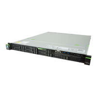
Fujitsu PRIMERGY RX100 S8 Upgrade And Maintenance Manual (296 pages)
Brand:
Fujitsu
| Category:
Server
| Size: 10.6 MB
Table of Contents
Copyright and Trademarks
2
Version History
6
Table of Contents
7
1 Introduction
19
Notational Conventions
20
2 Before You Start
21
Classification of Procedures
23
Customer Replaceable Units (CRU)
23
Upgrade and Repair Units (URU)
24
Field Replaceable Units (FRU)
25
Average Task Duration
26
Tools You Need at Hand
27
Documents You Need at Hand
28
3 Important Information
31
Safety Instructions
31
Energy Star
39
CE Conformity
39
FCC Class a Compliance Statement
40
Environmental Protection
41
4 Basic Hardware Procedures
43
Using Diagnostics Information
43
Locating the Defective Server
43
Determining the Error Class
44
Global Error Indicator
44
Customer Self Service (CSS) Indicator
44
Locating the Defective Component
45
Local Diagnostic Indicators on the System Board
45
Shutting down the Server
45
Disconnecting the Server from the Mains
46
Getting Access to the Component
47
Extending the Server out of the Rack
48
Removing the Server from the Rack
49
Removing the Top Cover
51
Reassembling
52
Installing the Top Cover
52
Mounting the Server in the Rack
53
Sliding the Server into the Rack
55
Connecting the Server to the Mains
55
Switching on the Server
57
Handling Riser Modules
58
Removing a Riser Module
58
Installing a Riser Module
60
5 Basic Software Procedures
63
Starting the Maintenance Task
63
Disabling Bitlocker Functionality
63
Disabling SVOM Boot Watchdog Functionality
64
Viewing Boot Watchdog Settings
64
Configuring Boot Watchdog Settings
65
Removing Backup and Optical Disk Media
66
Verifying and Configuring the Backup Software Solution
66
Note on Server Maintenance in a Multipath I/O Environment
67
Switching on the ID Indicator
69
Completing the Maintenance Task
70
Updating or Recovering the System Board BIOS and Irmc
70
Updating or Recovering the System Board BIOS
70
Updating or Recovering the Irmc
71
Verifying System Information Backup / Restore
73
Updating RAID Controller Firmware
74
Enabling Option ROM Scan
75
Verifying and Configuring the Backup Software Solution
76
Resetting the Boot Retry Counter
76
Viewing the Boot Retry Counter
77
Resetting the Boot Retry Counter
77
Enabling SVOM Boot Watchdog Functionality
78
Enabling Replaced Components in the System BIOS
79
Verifying the Memory Mode
80
Verifying the System Time Settings
80
Viewing and Clearing the System Event Log (SEL)
81
Viewing the SEL
81
Clearing the SEL
82
Updating the NIC Configuration File in a Linux Environment
83
Enabling Bitlocker Functionality
84
Performing a RAID Array Rebuild
85
Looking up Changed MAC / WWN Addresses
85
Looking up MAC Addresses
85
Looking up WWN Addresses
86
Using the Chassis ID Prom Tool
87
Configuring LAN Teaming
88
After Replacing / Upgrading LAN Controllers
88
After Replacing the System Board
88
Switching off the ID Indicator
89
Performing a Fan Test after Replacing a Defective Fan
89
6 Power Supply
91
Basic Information
92
Standard Power Supply
93
Replacing the Standard Power Supply Unit
93
Preliminary Steps
93
Removing the Defective Standard Power Supply Unit
93
Installing the New Standard Power Supply Unit
95
Concluding Steps
96
Redundant Power Supply
97
Installing a Hot-Plug Power Supply Unit
97
Preliminary Steps
97
Removing the Dummy Cover
97
Installing a Hot-Plug Power Supply Unit
98
Concluding Steps
99
Removing a Hot-Plug Power Supply Unit
99
Preliminary Steps
100
Removing a Hot-Plug Power Supply Unit
100
Installing the Dummy Cover
101
Replacing a Hot-Plug Power Supply Unit
101
Preliminary Steps
102
Removing the Defective Hot-Plug Power Supply Unit
102
Installing the New Hot-Plug Power Supply Unit
103
Concluding Steps
103
Replacing the Power Distribution Board
103
Preliminary Steps
103
Removing the Defective Power Distribution Board
104
Installing the New Power Distribution Board
105
Concluding Steps
106
Converting a Standard Power Supply to a Redundant Power Supply
106
Preliminary Steps
107
Removing the Standard Power Supply Unit
107
Installing the Upgrade Kit
108
Concluding Steps
112
7 Hard Disk Drives / Solid State Drives
113
Basic Information
114
Inch HDD/SSD Configurations
115
Equipping the 2.5-Inch HDD/SSD Bays
115
Configuration with up to Four HDD/SSD Modules
115
Configuration with up to Eight HDD/SSD Modules
116
Configuration with up to 10 HDD/SSD Modules
117
Installing 2.5-Inch HDD/SSD Modules
118
Preliminary Steps
118
Removing a 2.5-Inch HDD/SSD Dummy Module
118
Installing a 2.5-Inch HDD/SSD Module
119
Concluding Steps
120
Removing 2.5-Inch HDD/SSD Modules
120
Preliminary Steps
120
Removing a 2.5-Inch HDD/SSD Module
121
Installing a 2.5-Inch HDD/SSD Dummy Module
122
Concluding Steps
122
Replacing a 2.5-Inch HDD/SSD Module
122
Preliminary Steps
123
Removing the Defective 2.5-Inch HDD/SSD Module
123
Installing the New 2.5-Inch HDD/SSD Module
123
Concluding Steps
123
Replacing the 4 X 2.5-Inch HDD Backplane
124
Preliminary Steps
124
Removing the Defective 4 X 2.5-Inch HDD Backplane
124
Installing the New 4 X 2.5-Inch HDD Backplane
126
Concluding Steps
129
Replacing the 10 X 2.5-Inch HDD Backplane
130
Preliminary Steps
130
Removing the SAS Expander Board
130
Removing the Defective 10 X 2.5-Inch HDD Backplane
132
Installing the New 10 X 2.5-Inch HDD Backplane
133
Installing the SAS Expander Board
133
Concluding Steps
135
Replacing the SAS Expander Board
136
Preliminary Steps
136
Removing the Defective SAS Expander Board
136
Installing the New SAS Expander Board
136
Concluding Steps
136
Upgrading Configuration from up to Four to up to Eight 2.5-Inch Hdds/Ssds
137
Preliminary Steps
137
Installing the Second HDD Backplane
137
Installing Additional HDD/SSD Modules
138
Concluding Steps
138
Inch HDD Configurations
139
Equipping the 3.5-Inch HDD Bays
139
Installing 3.5-Inch HDD Modules
140
Preliminary Steps
140
Removing a 3.5-Inch HDD Dummy Module
140
Installing a 3.5-Inch HDD Module
141
Concluding Steps
141
Removing 3.5-Inch HDD Modules
142
Preliminary Steps
142
Removing a 3.5-Inch HDD Module
143
Installing a 3.5-Inch Dummy Module
143
Concluding Steps
143
Replacing a 3.5-Inch HDD Module
144
Preliminary Steps
144
Removing the Defective 3.5-Inch HDD Module
145
Installing the New 3.5-Inch HDD Module
145
Concluding Steps
145
Replacing the 3.5-Inch HDD Backplane
145
Preliminary Steps
145
Removing the Defective 3.5-Inch HDD Backplane
145
Installing the New 3.5-Inch HDD Backplane
146
Concluding Steps
147
8 Fans
149
Basic Information
149
Numbering of the Fan Modules
150
Replacing a Defective Fan Module
150
Preliminary Steps
150
Removing the Defective Fan Module
151
Installing the New Fan Module
152
Concluding Steps
153
9 Expansion Cards and Backup Units
155
Basic Information
156
Equipping the Pcie Slots
156
Handling Slot Brackets
159
Installing a Slot Bracket
159
Removing a Slot Bracket
164
Removing the Slot Bracket
164
Handling SFP+ Transceiver Modules
165
Installing SFP+ Transceiver Modules
165
Removing an SFP+ Transceiver Module
168
Expansion Cards and Riser Cards
171
Installing an Expansion Card
171
Preliminary Steps
171
Removing the Slot Cover
171
Installing the Expansion Card
172
Concluding Steps
172
Removing an Expansion Card
173
Preliminary Steps
173
Removing the Expansion Card
173
Installing the Slot Cover
174
Concluding Steps
174
Replacing an Expansion Card
175
Preliminary Steps
175
Removing the Defective Expansion Card
175
Installing the New Expansion Card
176
Concluding Steps
176
Replacing a Riser Card
177
Preliminary Steps
177
Removing the Defective Riser Card
177
Installing the New Riser Card
178
Concluding Steps
178
Replacing TFM
179
Preliminary Steps
179
Removing the Defective TFM
179
Installing the New TFM
180
Concluding Steps
180
Upgrading to the Full Height Riser Module
181
Preliminary Steps
181
Installing the Upgrade Kit
182
Backup Units (BBU/FBU)
185
Installing a BBU
185
Preliminary Steps
185
Connecting the BBU Cable to the BBU
186
Installing the BBU in the Holder
187
Installing the BBU with the Holder
188
Concluding Steps
190
Installing an FBU
191
Preliminary Steps
191
Installing TFM to the RAID Controller (if Applicable)
191
Installing the FBU in the Holder
192
Connecting the FBU Adapter Cable to the FBU
193
Installing the FBU with the Holder
193
Connecting the FBU Adapter Cable to the TFM
194
Concluding Steps
195
Removing a BBU
195
Preliminary Steps
195
Removing the BBU with the Holder
196
Removing the BBU from the Holder
196
Disconnecting the BBU Cable from the BBU
197
Concluding Steps
197
Removing an FBU
197
Preliminary Steps
198
Removing the FBU with the Holder
198
Disconnecting the FBU Cable from the FBU
198
Removing the FBU from the Holder
199
Concluding Steps
199
Replacing a BBU
199
Preliminary Steps
200
Removing the Defective BBU
200
Installing the New BBU
200
Concluding Steps
200
Replacing an FBU
201
Preliminary Steps
201
Removing the Defective FBU
202
Installing the New FBU
202
Concluding Steps
202
10 Main Memory
203
Basic Information
204
Memory Sequence
205
Population Rules
205
Modes of Operation
206
Installing a Memory Module
207
Preliminary Steps
207
Selecting the Memory Slot
207
Concluding Steps
208
Removing a Memory Module
208
Preliminary Steps
208
Removing a Memory Module
209
Concluding Steps
209
Replacing a Memory Module
209
Preliminary Steps
209
Removing the Defective Memory Module
210
Installing the New Memory Module
210
Concluding Steps
210
11 Processor
211
Basic Information
212
Supported Processors
212
Replacing the Processor
212
Preliminary Steps
213
Removing the Heat Sink
213
Removing the Defective Processor
214
Installing the New Processor
215
Applying the Thermal Paste to the Processor Surface
216
Installing the Heat Sink
218
Concluding Steps
218
Replacing the Heat Sink
219
Preliminary Steps
219
Removing the Defective Heat Sink
219
Installing the New Heat Sink
219
Concluding Steps
220
12 Optical Disk Drive
221
Basic Information
222
Installing the ODD
223
Preliminary Steps
223
Removing the Dummy Cover
224
Installing the ODD
225
Concluding Steps
226
Removing the ODD
227
Preliminary Steps
227
Installing the Dummy Cover
229
Concluding Steps
229
Replacing the ODD
230
Preliminary Steps
230
Removing the Defective ODD
230
Installing the New ODD
230
Concluding Steps
230
13 Front Panel
231
Basic Information
231
Replacing the Front Panel Module
232
Preliminary Steps
232
Removing the Front Panel Module
233
Installing the Front Panel Module
235
Concluding Steps
237
Replacing the Front Panel on QRL
238
Preliminary Steps
238
Removing the Front Panel on QRL
239
Installing the Front Panel on QRL
241
Concluding Steps
242
14 System Board and Components
243
Basic Information
243
CMOS Battery
244
Replacing the CMOS Battery
244
Preliminary Steps
244
Replacing the Defective CMOS Battery
245
Concluding Steps
245
USB Flash Module (UFM)
246
Installing the UFM
246
Preliminary Steps
246
Concluding Steps
247
Software Configuration
248
Removing the UFM
248
Preliminary Steps
248
Removing the UFM
249
Concluding Steps
250
Replacing the UFM
251
Preliminary Steps
251
Removing the Defective UFM
251
Installing the New UFM
252
Concluding Steps
252
Software Configuration
253
Trusted Platform Module (TPM)
253
Installing the TPM
253
Preliminary Steps
253
Installing the TPM
254
Concluding Steps
256
Removing the TPM
257
Preliminary Steps
257
Removing the TPM
259
Concluding Steps
260
Replacing the TPM
261
Preliminary Steps
261
Removing the Defective TPM
262
Installing the New TPM
262
Concluding Steps
262
System Board
263
Replacing the System Board
263
Preliminary Steps
265
Removing the Defective System Board
266
Installing the New System Board
267
Concluding Steps
268
15 Cables
271
Overview Cables
271
Cabling
272
16 Appendix
279
Mechanical Overview
279
Server Front
279
Server Rear
281
Server Interior
282
Connectors and Indicators
284
Connectors and Indicators on the System Board
284
Onboard Connectors
284
Onboard Indicators and Controls
286
I/O Panel Connectors
288
I/O Panel Indicators
288
Indicators on Hot-Plug Power Supply Units (Slide-In Units)
289
Indicators on the Front Panel
290
Indicators on the Accessible Drives/Components
293
Onboard Settings
294
Minimum Startup Configuration
295
Advertisement
Fujitsu PRIMERGY RX100 S8 Operating Manual (82 pages)
Brand:
Fujitsu
| Category:
Server
| Size: 1.43 MB
Table of Contents
Copyright and Trademarks
2
Table of Contents
7
1 Introduction
11
Concept and Target Groups for this Manual
11
Documentation Overview
12
Notational Conventions
13
2 Functional Overview
15
Features
15
Server Specification
24
3 Installation Steps, Overview
31
4 Important Information
33
Safety Instructions
33
Energy Star
41
CE Conformity
41
FCC Class a Compliance Statement
42
Transporting the Server
43
Notes on Installing the Server in the Rack
44
Environmental Protection
45
5 Hardware Installation
47
Unpacking the Server
48
Installing/Removing the Server In/From the Rack
49
Connecting Devices to the Server
51
Connecting the Monitor
53
Connecting the Server to the Mains
53
Using Cable Ties (Standard PSU)
54
Using the Cable Clamps (Hot-Plug PSU)
55
Notes on Connecting/Disconnecting Cables
56
6 Starting up and Operation
59
Control Elements and Indicators
59
Front of the Server
59
ID Card
60
Control Elements
60
Indicators on the Control Panel
61
Indicators on the Accessible Drives/Components
64
Rear of Server
65
Led Indicator Description
66
Switching the Server on and off
68
Configuring the Server
70
Configuring the Onboard SATA Controller
70
Configuring the SAS/SATA RAID Controller
71
Configuring the Server and Installing the Operating System with the Serverview Installation Manager
72
Configuring the Server and Installing the Operating System Without the Serverview Installation Manager
73
Cleaning the Server
74
7 Property and Data Protection
75
BIOS Setup Security Functions
75
8 Troubleshooting and Tips
77
Power-On Indicator Remains Unlit
77
Server Switches Itself off
78
Screen Remains Blank
78
Flickering Stripes on Monitor Screen
79
No Screen Display or Display Drifts
79
No Mouse Pointer Displayed on Screen
79
Incorrect Date and Time
80
Drives Reported as "Dead" When Starting System
80
Added Drive Reported as Defective
80
Error Message on Screen
81
Expansion Cards or Onboard Devices Not Recognized
81
Temperature Warning
81
No Effect of Keyboard or Mouse
81
Optical Drive Cannot Read Data
82
Advertisement
Related Products
Fujitsu PRIMERGY RX100 S7
Fujitsu Primergy RX100 S3
Fujitsu Primergy RX100 S4
Fujitsu Primergy RX100 S5
Fujitsu Primergy RX100 S2
Fujitsu PRIMERGY RX100 S6
Fujitsu PRIMERGY RX100
Fujitsu PRIMERGY RX1330 M2
Fujitsu PRIMERGY RX1330 M3
Fujitsu PRIMERGY RX1330 M5
Fujitsu Categories
Air Conditioner
Laptop
Server
Scanner
Storage
More Fujitsu Manuals
Login
Sign In
OR
Sign in with Facebook
Sign in with Google
Upload manual
Upload from disk
Upload from URL