Sign In
Upload
Manuals
Brands
Fronius Manuals
Inverter
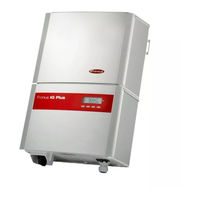
IG Plus A 7.5-1 UNI
Fronius IG Plus A 7.5-1 UNI Manuals
Manuals and User Guides for Fronius IG Plus A 7.5-1 UNI. We have
2
Fronius IG Plus A 7.5-1 UNI manuals available for free PDF download: Operating Instructions Manual
Fronius IG Plus A 7.5-1 UNI Operating Instructions Manual (180 pages)
Inverter for grid-connected photovoltaic systems
Brand:
Fronius
| Category:
Inverter
| Size: 9.98 MB
Table of Contents
Save These Instructions
5
Table of Contents
7
Safety Rules
11
Protection of Persons and Equipment
15
Safety
15
Galvanic Isolation
15
Monitoring the Grid
15
Information on "Field Adjustable Trip Points" and "Advanced Grid Features
15
FCC Compliance
16
Ground Fault Detector / Interrupter
16
Arc Detection / Interruption
16
Standards and Regulations
16
Declaration of Conformity
16
Warning Notice on the Wall Bracket
17
Warning Notices Affixed to the Device
17
The Inverter in the PV System
18
General
18
Tasks
18
Converting DC to AC Current
18
Fully Automatic Operation Management
18
Display Function and Data Communication
19
Data Communications Components
19
Forced Ventilation
19
Power Derating
19
Installing and Connecting Inverter
20
Safety
20
Inverter Construction
20
Connection Diagram
21
Overview
21
Connection Options
22
Fronius Arc Blocker' Plug-In Card
23
Knockouts
24
General
24
Knockouts for Wire Inputs
24
Choosing the Location
26
Choosing the Location in General
26
Choosing a Location for Inside Installation
27
Choosing a Location for Outdoor Installation
27
Installing the Inverter
28
General
28
Assembling the Wall Bracket
28
Recommended Screws for Wall Bracket Assembly
28
Attaching the Wall Bracket - Mounting Height
28
Attaching the Wall Bracket to a Concrete or Brick Wall
29
Attaching the Wall Bracket to a Wooden Wall
29
Installing a Wall Bracket on an Individual Column Outdoors
30
Attaching the Wall Bracket to a Metal Carrier
31
Lifting the Inverter
32
Inverter Installation
32
Installation of Several Inverters
34
Connecting the Inverter to the Public Grid (AC)
35
Overview of Available Grids
35
Monitoring the Grid
37
Systems with more than One Inverter
37
AC-Side Terminals and Grounding Terminals
38
Cross Section of AC Wires
39
Delta: 277 WYE Neutral Conductor Sizing
39
Safety
39
Connecting the Inverter to the Public Grid (AC)
40
Connecting Grounding Electrode Wire
41
AC-Side Overcurrent Protection
42
Additional External AC And/Or DC Disconnect
42
Connecting Solar Module Strings to the Inverter (DC)
43
General Information about Solar Modules
43
Safety
43
DC Terminals
43
Polarity Reversal of Solar Module Strings
44
Overview
44
Connecting Solar Module Strings
45
Solar Module Ground
45
Wire Cross Section of Solar Module Strings
45
Connecting Solar Module Strings
46
Inserting String Fuses
48
Connecting Combined Solar Module Strings Using Connecting Distributors
50
General
50
Additional Components Required
50
Solar Module Ground
50
Safety
51
Connecting Combined Solar Module Strings Using Connecting Distributors
51
Solar Module Ground at Positive Pole: Connecting Solar Module Strings
54
General
54
Solar Module Ground at Positive Pole
54
Wire Cross Section of Solar Module Strings
54
Solar Module Ground at Positive Pole: Connecting Solar Module Strings
55
Inserting String Fuses
60
Solar Module Ground at Positive Pole: Connecting Combined Solar Module Strings Using Connecting Distributors
61
General
61
Additional Components Required
61
Solar Module Ground at Positive Pole
61
Distributors
61
Safety
62
Criteria for the Proper Selection of String Fuses
67
DC Disconnect Requirements
67
General
67
Effects of Using Underrated Fuses
67
Fuse Recommendations
67
Application Example
68
Fuses
68
Attaching Power Stage Sets and Closing the Inverter
69
Preparation
69
Commissioning
70
Factory Pre-Set Configuration
70
Requirements for Start-Up Operation
70
Selecting the Grid
71
Startup Phase During Startup Operation
73
Setting Inverter for Solar Module Ground at the Positive Pole
75
Inserting Option Cards
77
Suitable Option Cards
77
Safety
77
Opening the Inverter
77
Inserting Option Cards into the Inverter
78
Termination Plug When Networking Several DATCOM Components
78
Connecting Option Cards, Laying Data Communication Wires
79
Closing the Inverter
80
Data Communication and Solar Net
81
Solar Net and Data Interface
81
Example
81
Selecting the Interface Protocol and Setting the Inverter Baud Rate
83
General
83
Entering the Access Code
83
Setting the Inverter Baud Rate
85
Product Description
88
Controls and Indicators
88
Display
88
Operating Status LED
90
Startup Phase and Grid Feed-In Mode
91
Startup Phase
91
Test Procedure
91
Operation of Feeding Energy into the Grid
92
Navigation in the Menu Level
93
Activating Display Illumination
93
Accessing the Menu Level
93
The Display Modes
94
Selecting a Display Mode
94
Overview of Display Values
95
Display Values in "Now" Display Mode
96
Selecting the "Now" Display Mode
96
Display Values in the 'Now' Display Mode
96
Options
97
Display Values in "Day / Year / Total" Display Modes
98
General
98
Selecting "Day / Year / Total" Display Mode
98
Display Values in the 'Day / Year / Total' Display Modes
99
Options
100
The Setup Menu
101
Presetting
101
Accessing the Setup Menu
101
Scrolling through Menu Items
102
Menu Items in the Setup Menu
103
Standby
103
Contrast
103
Light Mode
104
Cash
104
Co2
104
Yield
105
IG no
105
Dat Com
106
Afd
106
Time
107
State Ps
107
Version
107
Setting and Displaying Menu Items
108
Setting Menu Items - General
108
Examples of Setting and Displaying Menu Items
108
Setting the Currency and Rate
108
Displaying and Setting Parameters in the "DATCOM" Menu Item
110
Setting Time and Date
112
Setup Lock Function
115
General
115
Activating/Deactivating the "Setup Lock" Function
115
Status Diagnosis and Troubleshooting
117
Displaying Status Codes
117
Normal Operation Status Codes
117
Total Failure
117
Status Codes on Inverters with Several Power Stage Sets
118
Class 1 Status Codes
119
Class 2 Status Codes
120
Class 3 Status Codes
123
Class 4 Status Codes
125
Class 5 Status Codes
132
Customer Service
135
Maintenance
136
Safety
136
General
136
Operation in Dusty Environments
136
Opening the Inverter for Service/Maintenance
137
Replacing String Fuses
138
Safety
138
Preparation
138
Replacing String Fuses
139
Closing the Inverter
139
Replacing GFDI Fuse
141
Safety
141
Preparation
141
Replacing GFDI Fuse
142
Closing the Inverter
143
Resetting the Inverter after a Detected Arc Using the Display
144
General
144
Initial Situation
144
Resetting the Inverter after a Detected Arc Using the Switch on the Fronius Arc Blocker Plug-In Card
146
General
146
Initial Situation
146
Safety
146
Preparation
147
Resetting the Inverter after a Detected Arc Using the Switch on the Fronius Arc Blocker Plug-In Card
147
Closing the Inverter
148
Technical Data
149
Fronius IG Plus a 3.0-1
149
Fronius IG Plus a 3.8-1
151
Fronius IG Plus a 5.0-1
153
Fronius IG Plus a 6.0-1
155
Fronius IG Plus a 7.5-1
157
Fronius IG Plus a 10.0-1
159
Fronius IG Plus a 10.0-3
161
Fronius IG Plus a 11.4-1
163
Fronius IG Plus a 11.4-3
165
Fronius IG Plus a 12.0-3
167
Field Adjustable Trip Points
169
Relevant Standards and Directives
170
Grid Failure
170
Warranty and Disposal
171
Fronius Manufacturer's Warranty
171
Disclaimer
171
Disposal
171
Advertisement
Fronius IG Plus A 7.5-1 UNI Operating Instructions Manual (175 pages)
for grid-connected photo-voltaic systems
Brand:
Fronius
| Category:
Inverter
| Size: 6.31 MB
Table of Contents
Save These Instructions
5
Safety Instructions
7
Table of Contents
11
General Information
17
Protection of Persons and Equipment
19
Safety
19
Galvanic Isolation
19
Monitoring the Grid
19
Information for Field Adjustable Trip Points
20
FCC Compliance
20
Ground Fault Detector / Interruptor
20
Standards and Regulations
20
Product Listings and Compliance
20
The Fronius IG Plus Unit in the PV System
21
General Information
21
Tasks
21
Converting DC into AC Current
21
Fully Automatic Operation Management
21
Display Function and Data Communication
22
System Upgrades
22
Forced Ventilation
22
Power Derating
23
Installation and Startup
25
Fronius IG Plus Installation and Connection
27
Safety
27
Fronius IG Plus Construction
27
Connection Diagramm
28
Overview
28
Fronius IG Plus Connection Options
29
Knockouts on the Fronius IG Plus
31
General
31
Knockouts for Wire Inputs
31
Choosing the Location
33
Choosing the Location General
33
Choosing a Location for Inside Installation
33
Choosing a Location for Outside Installation
34
Fronius IG Plus Installation
35
General
35
Assembling the Wall Bracket
35
Recommended Screws for Wall Bracket Assembly
35
Attaching the Wall Bracket - Mounting Height
35
Attaching the Wall Bracket to a Concrete or Brick Wall
36
Attaching the Wall Bracket to a Wooden Wall
36
Attaching the Wall Bracket to a Metal Carrier
37
Fronius IG Plus Installation
37
Installation of Several Inverters
38
Connecting the Fronius IG Plus to the Public Grid (AC)
39
Overview of Available Power Grids
39
Monitoring the Grid
41
Schemes with more than One Inverter
41
AC-Side and Grounding Terminals
42
Cross Section of AC Wires
43
Safety
43
Connecting the Fronius IG Plus to the Public Grid (AC)
44
Connecting Grounding Electrode Wire
45
Recommendation for the AC-Side over Current Protection
45
Additional External AC And/Or DC Disconnect
45
Connecting Solar Module Strings to the Fronius IG Plus (DC)
46
General Information about Solar Modules
46
Safety
46
DC-Terminals
47
Overview
47
Connecting Solar Module Strings
48
Solar Module Ground
48
Wire Cross Section of Solar Module Strings
48
Connecting Solar Module Strings
49
Inserting String Fuses into the Fronius IG Plus
51
Criteria for the Proper Selection of String Fuses
52
DC Disconnect Requirements
52
General
52
Effects of Using Underrated Fuses
52
Fuse Recommendations - Application Example
53
Fuses
53
Additional Required Components
54
Solar Module Ground
54
Connecting Combined Solar Module Strings Using a DC String Input Combiner
54
General
54
Connecting Combined Solar Module Strings Using a DC String Input Combiner
55
Safety
55
Solar Module Ground at Positive Pole: Connecting Solar Module Strings
58
General
58
Wire Cross Section of Solar Module Strings
58
Solar Module Ground at Positive Pole
58
Solar Module Ground at Positive Pole: Connecting Solar Module Strings
59
Solar Module Ground at Positive Pole: Inserting String Fuses into the Fronius IG Plus
61
Criteria for the Proper Selection of String Fuses
63
DC Disconnect Requirements
63
General
63
Effects of Using Underrated Fuses
63
Fuse Recommendations - Application Example
64
Fuses
64
Solar Module Ground at Positive Pole: Connecting Combined Solar Module Strings Using a DC String Input Combiner
65
General
65
Additional Required Components
65
Solar Module Ground at Positive Pole
65
Solar Module Ground at Positive Pole: Connecting Combined Solar Module
65
Strings Using a DC String Input Combiner
66
Safety
66
Attaching Power Stage Sets and Closing the Fronius IG Plus
69
Preparation
69
Opening the Fronius IG Plus for Service/Maintenance
69
Start up Operation
70
Factory Pre-Set Configuration
70
Requirements for Starting up Operation
70
Selecting the Public Grid
71
Startup Phase at Startup Operation
73
Inserting Option Cards
75
Suitable Option Cards
75
Safety
75
Opening the Fronius IG Plus
75
Inserting Option Cards
76
Connecting Option Cards, Laying Data Communication Wires
76
Solar Net and Data Interface
78
Closing the Fronius IG Plus
78
Example
79
Operation
81
Product Description Fronius IG Plus
83
Keys and Symbols
83
Display
83
Test Procedure
85
Startup Phase
85
Operating Status LED
87
Operating Scheme - the Display
89
Activating
89
Display Illumination
89
Accessing Menus
89
Selecting a Display Mode
90
Scrolling between Display Functions
90
Overview of Display Values
91
Display Modes
92
Overview
92
Within Display Mode 'Now' Displayed Data
93
Selecting Display Mode 'Now
93
Options
95
Within Display Modes 'Day / Year / Total' Displayed Data
96
General
96
Selecting Display Modes 'Day / Year / Total
96
Within Display Modes 'Day / Year / Total' Displayed Data
97
Options
99
The Setup Menu
100
Default Settings
100
Enter the Setup Menu
100
Scrolling Among Menu Items
101
Menu Items in the Setup Menu
101
Setting and Displaying Menu Items
104
Menu Items Settings - General
104
Setting Menu Item 'Standby
104
Setting Menu Item 'Contrast
105
Setting Menu Item 'Lightmode
105
Setting Menu Item 'CASH
106
Setting Menu Item 'CO2
108
Setting Menu Item 'YIELD
109
Setting Menu Item 'IG-NR
112
Setting Menu Item 'Datcom
113
Setting Menu Item 'TIME
114
Displaying Menu Item 'Stateps
117
Displaying Menu Item 'Version
118
Troubleshooting and Maintenance
123
Status Diagnosis and Troubleshooting
125
Displaying Status Codes
125
Normal Operation Status Codes
125
Total Failure
125
Status Codes on Fronius IG Plus with Several Power Stage Sets
126
Class 1 Status Codes
126
Class 2 Status Codes
128
Class 3 Status Codes
129
Class 4 Status Codes
131
Class 5 Status Codes
138
Customer Service
140
Maintenance
141
Safety
141
General
141
Operation in Dusty Environments
142
Opening Fronius IG Plus for Service/Maintenance
142
Replacing String Fuses
143
Safety
143
Preparation
143
Replacing String Fuses
144
Closing Fronius IG Plus
145
Replacing GFDI Fuse
146
Safety
146
Preparation
146
Replacing GFDI Fuse
147
Closing Fronius IG Plus
148
Appendix
149
Technical Data
151
Fronius IG Plus 3.0-1
151
Fronius IG Plus 3.8-1
153
Fronius IG Plus 5.0-1
155
Fronius IG Plus 6.0-1
157
Fronius IG Plus 7.5-1
159
Fronius IG Plus 10.0-1
161
Fronius IG Plus 11.4-1
163
Fronius IG Plus 11.4-3
165
Fronius IG Plus 12.0-3
167
Field Adjustable Trip Points
169
Relevant Standards and Directives
170
Grid Failure
170
Warranty and Disposal
171
FRONIUS USA Limited 10-Year Warranty
171
Policy and Procedure for Warranty Returns and Repairs
171
Disposal of Obsolete Equipment - Recycling
172
Advertisement
Related Products
Fronius IG Plus A 3.0-1 UNI
Fronius IG Plus A 3.8-1 UNI
Fronius IG Plus A 10.0-1 UNI
Fronius IG Plus A 10.0-3 Delta
Fronius IG Plus A 11.4-1 UNI
Fronius IG Plus A 6.0-1 UNI
Fronius IG Plus A 5.0-1 UNI
Fronius IG Plus A 11.4-3 Delta
Fronius IG Plus 150 V-3
Fronius IG Plus 120 V-3
Fronius Categories
Welding System
Inverter
Welding Accessories
Battery Charger
Measuring Instruments
More Fronius Manuals
Login
Sign In
OR
Sign in with Facebook
Sign in with Google
Upload manual
Upload from disk
Upload from URL