Sign In
Upload
Manuals
Brands
Ford Manuals
Tractor
fordson dexta
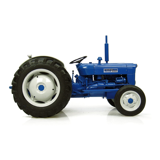
Ford fordson dexta Manuals
Manuals and User Guides for Ford fordson dexta. We have
1
Ford fordson dexta manual available for free PDF download: Shop Manual
Ford fordson dexta Shop Manual (140 pages)
Brand:
Ford
| Category:
Tractor
| Size: 45.9 MB
Table of Contents
Index
4
Front System and Steering
5
Spindle Bushings
5
Axle Center Member and Pivot Pin Bushing
5
Front Support
6
Drag Links and Toe-In
6
Steering Gear
6
To Remove the Steering Worm Shaft from Main Housing
6
Engine and Components
7
Steering Gear Removal/ Reinstallment/Overhaul
7
R&R Engine Assembly
8
Cylinder Head
8
Valves and Seats
8
Measuring Valve Head Clearance with Special Depth Gage
8
Valve Guides and Springs
9
Valve Tappets
9
Rocker Arm and Shaft
9
Timing Gear Cover and Gears
9
Timing Gears
10
Injection Pump Drive Gear
10
Timing the Gears
11
Camshaft
11
Connecting Rod and Piston Units
11
Pistons, Rings and Sleeves
11
Piston Pins
12
Connecting Rods and Bearings
12
Crankshaft and Main Bearings
12
Crankshaft Oil Seals
13
Flywheel
13
Oil Pump and Relief Valve
13
Diesel Fuel System
14
Engine Oil Pump Exploded View
14
Clearance between Rotors Check
14
Routine Servicing
15
Cutaway View of the Simms Multiple Plunger Injection Pump and Injectors
15
Troubleshooting
15
Engine will Not Start
15
Filters and Bleeding
16
Injector Assemblies
16
Engine Lacks Power/Knocks
16
Rough or Uneven Engine Operation
16
Testing and Locating a Faulty Nozzle
17
Spray Pattern
17
Seat Leakage/Nozzle Leak Back
17
Injector Overhaul
17
Injection Pump
18
Nozzle Cleaning
18
Injection Pump Timing/R&R
19
Vacuum Governor Adjust
19
Vacuum Governor Operation and Servicing
20
Intake Manifold View
20
"Minimec" Mechanical Governor, Adjust
20
Cooling System
21
Radiator
21
Water Pump
21
Primary Fuel Pump
21
Electrical System
22
Clutch/Clutch Pedal Adjustment
22
Generator and Regulator
22
Starting Motor
22
Tractor Split
23
R&R and Overhaul Clutch
23
Single Plate Models
23
Double Clutch Models
23
Aligning and Adjusting the Double Clutch During Reassembly
24
Center Drive Plate and Pto Clutch Illustration
24
Double Clutch Asssembly Illustration
24
Clutch Fingers Adjustment Illustration
24
Transmission
25
Cross-Sectional View of Transmission Assembly with Live Pto
25
Input Shaft Seal Renewal
26
Remove and Reinstall Transmission
26
Transmission Overhaul
26
Exploded View of Transmission Housing and Clutch Release Mechanism
26
Pto Countershaft and Rear Cover
27
Secondary Transmission
27
Exploded View of Secondary Transmisson and Pto Counter Shaft Assembly
27
Input Shaft Assembly
27
Main Transmission
28
Shifter Rails and Forks
28
Transmission Countershaft Showing Milled Flat Illustration
28
Exploded View of Shifter Rails and Forks
28
Differential, Bevel Gears and Rear Axle
29
Differential Removal/Reinstallation/Overhaul
29
Cutaway View of Final Drive Without Differential Lock
29
Front View of Rear Transmission Housing with Gears Removed
29
Cross-Sectional View of Differential Case and Ring Gear
30
Exploded View of Differential Lock and Related Parts
30
Differential Lock Operation and Adjustment
31
Differential Lock Overhaul
31
Operating Principles of Differential Lock Illustration
31
Adjusting the Differential Lock Illustration
31
Main Drive Bevel Pinion
32
Rear Axle Shaft, Bearings and Seals
32
Differential Lock Coupling View
32
Rear Axle Center Housing View
32
R&R Axle Assembly
33
Overhaul Axle Assembly
33
Rear Axle Assembly Exploded View
33
Brake System Adjustment
34
R&R Brake Shoes
34
Power Take-Off
34
Output Shaft
34
Belt Pulley Overhaul
35
Shifter Unit
35
Pto Sliding Connector
35
Rear Pto Train Sectional View
35
Hydraulic Lift System/Troubleshooting
36
Schematic View of Oil Flow with Control Valve in Neutral Position
36
Control Adjustments - Main Control Spring
37
Draft Control
37
Bobbing (Hiccups)
37
Over-Correction in Draft Control
37
Lift Cover and Cylinder Overhaul
38
Ford NAA Locating Arm View
38
Adjusting Control Valve for Constant Draft Position
38
Check Valve and Seat
39
Cylinder Safety Valve
39
Accessory Plate
39
Flow Control Valve
39
Exploded View of Early Fordson Dextra Hydraulic Lift Cover, Cylinder and Linkage
40
Lift Cylinder
40
Cylinder R&R and Inspect
40
R&R Control Valve and Bushing (Used 11/5760/10)
41
R&R Control Valve and Bushing (Used 10/60/-)
41
Exploded View of Late Hydraulic Lift Cover, Cylinder and Linkage
41
Selecting Proper Size of Control Valve and Bushing
42
Unloading Valve Bushings, Plug, Valve and "O" Ring Size Selection
42
Flow Conrol Valve Exploded View
42
Threaded Rod Type Push Puller View
42
Hydraulic Pump
43
Pressure Relief Valve
43
Rock Shaft and Control Linkage
43
Return Line, Filter and Back Pressure Valve
43
Exploded View of Hydraulic Pump Assembly with Intake Strainer
44
Exploded Views of Early/Late Production Pressure Relief Valve Assembly
44
Parts Arrangement When Assembling Pump
44
Hydraulic Pump Removal/Reinstallment/Overhaul
45
Assembly Procedure of the Hydraulic Pump Gears and Bearings
45
Fordson Major Tractor Series Serial Numbers
48
Models FMD, FPM, FSM, New FSM Index
49
FMD, FPM, FSM, New FSM: Condensed Service Data
50
FMD, FPM, FSM, New FSM: Front System, Axle Type
51
Wheel Assembly/Spindles
51
Axle Extensions
51
Axle Center Member, Pivot Pin and Bushing
51
Front System, Trycicle
52
Tie Rod and Toe-In
52
Radius Rod, Rear Pivot Pin and Bushing/Front Support
52
FMD, FPM, FSM, New FSM: Steering Gear
53
FMD, FPM, FSM, New FSM: Cross Shaft and Front Support
53
FMD, FPM, FSM, New FSM: Cross-Sectional View of Tricycle Front Pedestal
53
FMD, FPM, FSM, New FSM: Exploded View of Typical Steering Gear Assembly for Adjustable Front Axle Models
54
FMD, FPM, FSM, New FSM: Seal Retainer View
54
FMD, FPM, FSM, New FSM: Power Steering
55
FMD, FPM, FSM, New FSM: Fluid and Bleeding
55
FMD, FPM, FSM, New FSM: System Operating Pressure
55
FMD, FPM, FSM, New FSM: Pump and Reservoir
55
FMD, FPM, FSM, New FSM: Exploded View of the Power Steering Pump and Reservoir Assembly
56
FMD, FPM, FSM, New FSM: Measuring Drive Rotor to Driven Rotor Tooth Clearance/Rotor End Clearance
56
FMD, FPM, FSM, New FSM: Cylinder and Control Valve Assembly
57
FMD, FPM, FSM, New FSM: Exploded View of Later Production Power Steering Cylinder and Control Valve Assembly for Wide Front Axle Models
58
FMD, FPM, FSM, New FSM: Engine and Components
59
FMD, FPM, FSM, New FSM: R&R Engine and Clutch Assembly
59
Cross-Sectional View of Late Type Bearings Assembly
59
Cross-Sectional View of Cylinder and Control Valve Assembly
59
FMD, FPM, FSM, New FSM: Cylinder Head
60
FMD, FPM, FSM, New FSM: Rocker Arms and Shaft
61
FMD, FPM, FSM, New FSM: Valves and Valve Seats
62
FMD, FPM, FSM, New FSM: Valve Guides/Stem Seals
62
FMD, FPM, FSM, New FSM: Exhaust Valve Rotators
62
FMD, FPM, FSM, New FSM: Valve
63
FMD, FPM, FSM, New FSM: Exhaust Valve Spring Spacers
63
FMD, FPM, FSM, New FSM: Timing Gear Cover/Timing Gears
63
FMD, FPM, FSM, New FSM: Feeler Stock Method of Checking End Clearance between Rotator Cap and End of Valve Stem
63
FMD, FPM, FSM, New FSM: Engine Front Plate
64
FMD, FPM, FSM, New FSM: Timing Gear Width
64
FMD, FPM, FSM, New FSM: Timing Marks on Timing Gears View
64
FMD, FPM, FSM, New FSM: Cam Followers (Valve Tappets)
65
FMD, FPM, FSM, New FSM: Camshaft and Bearings
65
FMD, FPM, FSM, New FSM: Timing Gears Views
66
FMD, FPM, FSM, New FSM: Thrust Washer View
66
FMD, FPM, FSM, New FSM: Auxiliary Driveshaft
67
FMD, FPM, FSM, New FSM: Camshaft Bearings
67
FMD, FPM, FSM, New FSM: Camshaft Rear Bearing Plug
67
FMD, FPM, FSM, New FSM: Connecting Rods and Pistons
68
FMD, FPM, FSM, New FSM: Piston Pins and Bushings
68
FMD, FPM, FSM, New FSM: Exploded View of Late Production Auxiliary Driveshaft Assembly
68
FMD, FPM, FSM, New FSM: Connecting Rods and Bearings
69
FMD, FPM, FSM, New FSM: Pistons and Rings
69
FMD, FPM, FSM, New FSM: Checking Piston to Cylinder Sleeve Fit with Feeler Gage and Pull Scale
69
FMD, FPM, FSM, New FSM: Cylinder Sleeves
70
FMD, FPM, FSM, New FSM: Crankshaft and Main Bearings
70
FMD, FPM, FSM, New FSM: Cross-Sectional Drawing of Spigoted Cylinder Sleeve Installed in Cylinder Block
70
FMD, FPM, FSM, New FSM: Checking Cylinder Sleeve Protruson with Dial Indicator
70
FMD, FPM, FSM, New FSM: Main Bearing Tightening Torques
71
FMD, FPM, FSM, New FSM: Crankcase Ventilation System
72
FMD, FPM, FSM, New FSM: Crankshaft Oil Seals
72
FMD, FPM, FSM, New FSM: Engine Oil Filter
73
FMD, FPM, FSM, New FSM: Oil Pump and Relief Valve
73
FMD, FPM, FSM, New FSM: Oil Pan (Sump)
74
FMD, FPM, FSM, New FSM: Cross-Sectional View of Late Type Pump
74
FMD, FPM, FSM, New FSM: Camshaft Front (Outer) Gear Removed View
74
FMD, FPM, FSM, New FSM: Diesel Fuel System
75
FMD, FPM, FSM, New FSM: Troubleshooting
75
FMD, FPM, FSM, New FSM: Flywheel
75
FMD, FPM, FSM, New FSM: Filters and Bleeding
76
FMD, FPM, FSM, New FSM: View Showing Dual Filter Assembly Used with Simms Minimec Fuel Injection Pump Assembly
76
FMD, FPM, FSM, New FSM: View of Bleeding Fuel System with Vacuum Governor Fuel Injection Pump and Single Stage Filter
76
FMD, FPM, FSM, New FSM: Fuel Lift Pump
77
FMD, FPM, FSM, New FSM: Fuel Injection Pump
77
FMD, FPM, FSM, New FSM: Timing Chart (Vacuum Governor)
78
FMD, FPM, FSM, New FSM: View Showing Timing Mark on Fuel Injection Pump Drive Coupling Flange
78
FMD, FPM, FSM, New FSM: View of Fuel Injection Pump Showing the Excess Fuel Control Button
78
FMD, FPM, FSM, New FSM: Exploded View of Pump Drive Coupling
79
FMD, FPM, FSM, New FSM: Maximum Speed Screw and Idling Screw View
79
FMD, FPM, FSM, New FSM: Schematic View of the Vacuum Governor Unit Incorporated in the Simms Fuel Injection Pump
80
FMD, FPM, FSM, New FSM: Exploded View of the Fuel Injection Pump Vacuum Governor Assembly
80
FMD, FPM, FSM, New FSM: View Showing Vacuum Governor Assembly Being Removed from Fuel Injection Pump
80
FMD, FPM, FSM, New FSM: View Showing 10 Degree Taper and 20 Degree Taper Dampening Valves and Their Mating Bushings
80
Models with Mechanical Governor Type (Minimec) Fuel Injection Pump
81
FMD, FPM, FSM, New FSM: View Showing Throttle Plate and Shaft Removed from Intake Manifold
81
View of Simms Minimec Fuel Injection Pump on Fordson Super Major
81
FMD, FPM, FSM, New FSM: Injection Nozzles
82
FMD, FPM, FSM, New FSM: View of Oil Drain Plug, Level Plug and Filler Plug
82
FMD, FPM, FSM, New FSM: View of Fuel Injection Pump Removed from Engine to Show Maximum Speed Screw and Idling Stop Screw
82
FMD, FPM, FSM, New FSM: Checking Nozzle Seat Leakage on Injector Nozzle Test Stand View
83
FMD, FPM, FSM, New FSM: Adjusting Injector Opening Pressure View
83
FMD, FPM, FSM, New FSM: Cleaning Nozzle Pressure Chamber/Nozzle Spray Hole
84
FMD, FPM, FSM, New FSM: Removing Carbon from Valve Seat in Nozzle
84
FMD, FPM, FSM, New FSM: Clean Annular Groove in Top of Nozzle Using Pressure Chamber Tool
84
FMD, FPM, FSM, New FSM: Proper Positioning of Nozzle in Reverse Flush Adapter
84
FMD, FPM, FSM, New FSM: Cooling System
85
FMD, FPM, FSM, New FSM: Radiator
85
FMD, FPM, FSM, New FSM: Cross-Sectional View Showing Early Type Radiator Mounting
85
FMD, FPM, FSM, New FSM: Shim Washer Installed between Nozzle and Retaining Nut View
85
FMD, FPM, FSM, New FSM: Thermostat
86
FMD, FPM, FSM, New FSM: Water Pump
86
FMD, FPM, FSM, New FSM: Fan Blades
86
FMD, FPM, FSM, New FSM: Exploded View of Typical Water Pump Assembly
86
FMD, FPM, FSM, New FSM: Electrical System
87
FMD, FPM, FSM, New FSM: Generator/Test Procedure/Wiring Diagram
87
FMD, FPM, FSM, New FSM: Using Feeler Gage to Check Clearance between Pump Housing and Impeller
87
FMD, FPM, FSM, New FSM: Voltage Regulator
88
FMD, FPM, FSM, New FSM: Adjustment Points for Voltage Regulator Armature on Lucas Model RB 106/1
89
Adjustment on Lucas Model RB 106/2 Cut-Out Relay
89
FMD, FPM, FSM, New FSM: Cut-Out Relay Adjustment
89
FMD, FPM, FSM, New FSM: View of Voltage Regulator of Model RB 106/2 Lucas Regulator Assembly
90
FMD, FPM, FSM, New FSM: Exploded View of Starting Motor Assembly
90
FMD, FPM, FSM, New FSM: Clutch
91
FMD, FPM, FSM, New FSM: Tractor Split
91
FMD, FPM, FSM, New FSM: Starting Motor
91
FMD, FPM, FSM, New FSM: Adjusting Relay Switch Position
91
FMD, FPM, FSM, New FSM: Linkage Adjustment
92
FMD, FPM, FSM, New FSM: Exploded View of 11-Inch Diameter Single Clutch Assembly
92
FMD, FPM, FSM, New FSM: Exploded View of 13-Inch Single Clutch Assembly
93
Assembling Release Lever, Strut, Lever Pin and Eyebolt to Clutch Pressure Plate
93
Models with Dual ("Live PTO") Clutch
94
FMD, FPM, FSM, New FSM: Cross-Sectional View of 13-Inch Clutch Cover and Pressure Plate Assembly Mounted on Flywheel with Three Spacers
94
FMD, FPM, FSM, New FSM: Exploded View of Typical ("Live PTO") Clutch Assembly
95
FMD, FPM, FSM, New FSM: Removing Cover from Dual Clutch Assembly
95
FMD, FPM, FSM, New FSM: View Showing Early and Late Production Transmission Clutch Pressure Plate
96
FMD, FPM, FSM, New FSM: Installing Transmission Disc Pilot, PTO Disc Pilot, Gage Block, Washer and Nut View
96
FMD, FPM, FSM, New FSM: Mounting Dual Clutch Assembly on Spindle and Risers
96
FMD, FPM, FSM, New FSM: Attaching Spindle and Risers of Clutch Assembly and Adjustment Fixture to Engine Flywheel
96
FMD, FPM, FSM, New FSM: Automatic Clutch Release (ACR)
97
View Showing Early Production Automatic Clutch Release (ACR) Linkage
97
FMD, FPM, FSM, New FSM: Transmission
98
FMD, FPM, FSM, New FSM: Shifter Mechanism
98
FMD, FPM, FSM, New FSM: Lubrication
98
FMD, FPM, FSM, New FSM: Exploded View of Typical Automatic Clutch Release Cylinder and Three-Point Hitch Top Link Assembly
98
FMD, FPM, FSM, New FSM: View O Rear End of Primary Gearbox Assembly
99
FMD, FPM, FSM, New FSM: Exploded View of Main Transmission Shift Mechanism
99
FMD, FPM, FSM, New FSM: View Showing Latest Production Main Shift Rail Detents and Early Production Detents
99
FMD, FPM, FSM, New FSM: View of Inside of Shift Plate
99
FMD, FPM, FSM, New FSM: Transmissio Input (Clutch) Shaft
100
FMD, FPM, FSM, New FSM: View of Transmission with Planetary Gearbox Assembly and Main Shift Plate Assembly
100
FMD, FPM, FSM, New FSM: R&R Complete Transmission Assembly
100
FMD, FPM, FSM, New FSM: R&R Primary Gearbox
101
FMD, FPM, FSM, New FSM: Overhaul Primary Gearbox
101
FMD, FPM, FSM, New FSM: Exploded View of Primary Gearbox Assembly for Single Clutch Models
101
FMD, FPM, FSM, New FSM: View of Primary Gearbox Assembly
102
Early Model FMD Primary Gearbox Exploded View
103
Models with Dual Clutch
103
FMD, FPM, FSM, New FSM: Removing Primary Upper Shaft Gear and Bearing Assembly from Primary Gearbox
104
FMD, FPM, FSM, New FSM: Removing Upper Shaft Locking Plate from Primary Gearbox Housing
104
FMD, FPM, FSM, New FSM: Using Suitable Drift, Drive Lower Shaft from Bearing and Cluster Gear
104
FMD, FPM, FSM, New FSM: Main Transmission
105
FMD, FPM, FSM, New FSM: Cut-Away View of Typical Single Clutch Transmission
105
FMD, FPM, FSM, New FSM: View of Rear End of Main Transmission
106
FMD, FPM, FSM, New FSM: Measure Bore to Determine Proper Size of Plug
106
FMD, FPM, FSM, New FSM: Differential
107
FMD, FPM, FSM, New FSM: Carrier Bearing Adjustment
107
FMD, FPM, FSM, New FSM: Cross-Sectional View of Bevel Ring Gear
108
Cross-Sectional View of Model FSM and New FSM Differential, Bull Pinion and Right Brake Unit
108
FMD, FPM, FSM, New FSM: Main Drive Bevel Gears
109
FMD, FPM, FSM, New FSM: Ring Gear Thrust Pad
109
FMD, FPM, FSM, New FSM: Differential Lock
109
FMD, FPM, FSM, New FSM: Exploded View of Right Bull Pinion and Differential Lock Assembly
109
FMD, FPM, FSM, New FSM: Main Drive Bevel Pinion
110
FMD, FPM, FSM, New FSM: Cross-Sectional View Showing Bevel Pinion Mounting
110
FMD, FPM, FSM, New FSM: View Showing Bevel Ring Gear Thrust Pad and Support Assembly
110
FMD, FPM, FSM, New FSM: Cut-Away View of Bull Pinion Shaft and Housing
110
FMD, FPM, FSM, New FSM: Final Drive and Rear Axles
111
FMD, FPM, FSM, New FSM: Bull Pinions
111
Cut-Away View of Model FSM and New FSM Disc Brake, Bull Pinion and Differential Lock
111
FMD, FPM, FSM, New FSM: Bull Gears
112
FMD, FPM, FSM, New FSM: Rear Axles and Housings
112
FMD, FPM, FSM, New FSM: Removing Nut from Inner End of Rear Axle Illustration
112
FMD, FPM, FSM, New FSM: Removing Axle Shaft Inner Bearing from Hub of Bull Gear Illustration
112
FMD, FPM, FSM, New FSM: Brakes
113
View of Model FMD and FPM Brake Assembly with Brake Drum Cover and Drum Removed
113
View of Brake Backing Plate Assembly with Brake Shoes Removed
113
Minor Adjustment of Model FMD and FPM Brake Shoes Illustration
113
Exploded View of Model FSM and New FSM Right Brake Assembly and Actuating Pedals and Linkage
114
Adjusting Model FSM and New FSM Brakes Illustration
114
FMD, FPM, FSM, New FSM: Adjusting Disc Brake Free Pedal Illustration
114
FMD, FPM, FSM, New FSM: Belt Pulley
115
FMD, FPM, FSM, New FSM: Installing Brake Housing Illustration
115
FMD, FPM, FSM, New FSM: Power Take-Off
116
FMD, FPM, FSM, New FSM: PTO Drive Unit (Gearbox)
116
FMD, FPM, FSM, New FSM: Cross-Sectional View Showing PTO Drive Gear Train
116
FMD, FPM, FSM, New FSM: Standard PTO Output Shaft
117
FMD, FPM, FSM, New FSM: Exploded Viw of PTO Gearbox
117
FMD, FPM, FSM, New FSM: Exploded View of Standard PTO Output Shaft Assembly
117
FMD, FPM, FSM, New FSM: Cross-Sectional View of Latest Type PTO Idler Gear and Bearings Assembly
117
FMD, FPM, FSM, New FSM: Raised PTO Output Unit
118
FMD, FPM, FSM, New FSM: View of PTO Drive Shaft and Drive Gear with Raised PTO Assembly
118
Hydraulic System (Models FMD and FPM)
119
Pressure Gage Shut off Valve and Return Hose Installed to Check Hydraulic Relief Pressure on Models FMD and FPM
120
Early Type Pressure Relief Valve Assembly Illustration
120
View Showing Pressure Relief Valve Seat Removed from Bottom of Valve Housing
120
View Showing Control Valve Lever Support Split from Valve Housing
121
View Showing Late and Early Type Control Valve Spools
121
Views Showing Earlier Type and Latest Type Pressure Relief Valve Assemblies
121
Exploded View of Control Lever, Support and Control Valve Unit
122
Exploded View of Valve Housing Assembly with Control Lever Support and Control Valve Assembly Removed
122
Exploded View of Model FMD and FPM Hydraulic Lift Cover, Lift Shaft and Related Parts
123
Removing Check Valve and Guide Assembly from Bottom of Valve Housing
123
View Showing Cover Removed from Valve Housing
123
View Showing Lift Cylinder Piston Partially Installed in Cylinder
123
Models FMD and FPM: Position Control Attachment
124
Models FMD and FPM: Hydraulic Pump
124
Model FMD Hydraulic Pump Assembly Exploded View
124
FSM and New FSM: Hydraulic System
125
FSM and New FSM: Fluid and Filters
125
FSM and New FSM: Troubleshooting
126
Schematic Diagram of Model FSM Hydraulic System in Neutral Position
126
FSM and New FSM: System Relief Pressure
127
View of Controls on Model FSM Hydraulic System
127
View Showing Hydraulic Pressure Gage, Shut-Off Valve and Return Hose Installed on Model FSM for Hydraulic Relief Pressure Check
127
Model FSM: System Adjustments
128
Adjusting Model FSM Draft Control Linkage Illustration
128
Model New FSM System Adjustments
129
Adjusting Model FSM Position Control Linkage Illustration
129
View Showing Location of Drop Control Valve Knob on Model New FSM
129
Cut-Away View of Lift Cylinder Showing Drop Control Restrictor Valve
129
FSM and New FSM: Flow Control and Selector Valve Assembly
130
Drawing Showing Linkage Adjustment Points for Model New FSM
130
View of Model New FSM Control Linkage Showing Knock-Off Pin
130
FSM and New FSM: Lift Cover and Cylinder
131
Exploded View of Flow Control and Selector Valve Assembly
131
Removing Lift Cylinder from Model FSM Lift Cover Assembly Illustration
131
Exploded View of Model FSM Lift Cover Assembly
132
FSM and New FSM: R&R Lift Cylinder Assembly
132
Exploded View of Lift Cylinder Assembly for Model FSM
133
FSM and New FSM: Check Valve and Seat/System Relief Valve
133
FSM and New FSM: Cylinder Safety Valve/Drop Control Valve
133
FSM and New FSM: Control Valve and Bushing
133
FSM and New FSM: Control Valve Bushings/Spools
134
FSM and New FSM: Unloading Valve and Bushing
134
FSM and New FSM: Removing Position Control Linkage and Control Lever Shaft
134
Exploded View of Model FSM Position Control Linkage
134
FSM and New FSM: Hydraulic Control Linkage
135
FSM and New FSM: Lift Cylinder Piston
135
FSM and New FSM: Lift Arms, Shaft and Bushings
135
Exploded View of Model FSM and New FSM Hydraulic Pump Assembly
135
FSM and New FSM: Return Line, Filter and Back Pressure Valve
136
FSM and New FSM: Hydraulic Pump
136
Advertisement
Advertisement
Related Products
Ford fordson major diesel
Ford fordson power major
Ford F-1200
Ford Focus 2016
Ford focus c-max
Ford FOCUS 2017
Ford Focus ST 2017
Ford Focus 2021
Ford Focus
Ford FOCUS LV
Ford Categories
Automobile
Automobile Accessories
Engine
Tractor
Portable Generator
More Ford Manuals
Login
Sign In
OR
Sign in with Facebook
Sign in with Google
Upload manual
Upload from disk
Upload from URL