Sign In
Upload
Manuals
Brands
Fliegl Manuals
Farm Equipment
ASW 256
Fliegl ASW 256 Manuals
Manuals and User Guides for Fliegl ASW 256. We have
1
Fliegl ASW 256 manual available for free PDF download: Operating Instructions Manual
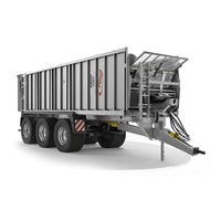
Fliegl ASW 256 Operating Instructions Manual (128 pages)
push-off trailer
Brand:
Fliegl
| Category:
Farm Equipment
| Size: 8.72 MB
Table of Contents
Foreword
3
Table of Contents
5
Contents
5
Legal Notices
11
Identification
12
EC Declaration of Conformity
13
1 User Instructions
14
Purpose of this Document
14
Locations in the Operating Instructions
15
Illustrations Used
15
Cross References
15
Terminology: "Trailer", "Machine", "Vehicle
15
Figures
15
Scope of the Document
16
Presentation of Safety Instructions
16
Liability and Damages
16
Duty to Inform
16
2 Basic Safety Instructions
17
Designated Use
20
Reasonably Foreseeable Misuse
21
Service Life of the Machine
22
Risks When Working with the Machine
22
Residual Risks
22
Obligations of the Operator
22
Obligations of Personnel
23
Qualification of Operating Personnel
23
Qualification of Specialist Personnel
23
Personal Protective Equipment
24
Operational Safety
24
Operation Without Correct Start-Up
24
Safeguarding Perfect Technical Condition
24
Danger Due to Machine Damage
24
Technical Limits
25
Safety and Protective Devices
25
Emergency Stop Device
25
Description of Additional Safety and Protective Devices
25
In Case of Faulty Protective Devices
25
Inspecting Safety and Protective Devices
25
Workstation of Operating Personnel
26
Danger Areas
26
Danger Zone Around PTO
27
Danger Zone Around Machine Parts that Continue Running
27
Safety Distance from Overhead Lines
27
Machine Identification
28
3 Description of the Machine
30
Applications
30
Design Variants - Standard
30
Functional Description
30
Layout of the Machine
31
Assemblies and Components
32
Technical Data - Standard Equipment
34
4 Transport and Installation
36
Basic Requirements
36
Supply and Installation
36
Drawbar Eye Connection
36
Establishing the Electrical Connection
37
Compressed Air Supply
38
Establishing Hydraulic Connections
39
5 Start-Up
41
First-Time Start-Up
41
Check before Start-Up
41
Returning to Service
41
6 Preparation and Setup
42
Draw Gear
42
Draw Gear with Top/Bottom Attachment
42
Hydraulically Sprung Draw Gear
42
Drawbar
43
Ball Head Coupling
43
Installing Forced Steering on the Towing Vehicle (Optional)
44
Setting up the Forced Steering (Optional)
46
Pressurised Air Suspension (Optional)
49
Compressed Air Brake System
50
Brake System with Manual Control Valve
50
Brake System with ALB, Brake Force Regulator
51
Brake System - Release Valve
51
Brake System with Combined Service/Parking Brake (Tristop)
52
Hydraulic Brake (Optional)
54
Hydraulic Brake Without Load Adjustment Valve
54
Hydraulic Brake with Load Adjustment Valve
54
Parking Brake
55
Spindle Brake / Parking Brake
55
Farmer Stop - Parking Brake
55
Hydraulic System
56
Standard Constant Flow Version (Open Centre, OC)
56
Additional Load Sensing (LS) Version [Also Known as "Power Beyond"]
56
Load Sensing or Constant Flow Operation
57
Setting the Flow Control Valve/Potentiometer (Optional)
58
Mechanical Flow Control Valve
58
Electrical Potentiometer
59
Manual Emergency Operation of the Hydraulic Control
60
Cause of Control Unit Malfunction
61
Adjusting the Grate Extension
61
Drive Shaft for Attachment (Optional)
62
Electrical Systems
62
7 Use and Operation
63
Trailer Operation
63
Before Operation
63
Setting up the Trailer Coupling on the Towing Vehicle
63
Coupling the Trailer
64
Attaching the Drive Shaft (Optional)
65
Detaching the Drive Shaft (Optional)
66
Electrical and Electronic Control Accessories
66
Conducting a Trial Run
67
Uncoupling the Trailer
67
Working with the Machine
68
General Safety and Operating Instructions
68
Loading the Trailer
69
Emptying the Trailer
70
Chassis Lock
71
Chassis Lock, Bolted
71
Chassis Lock, Twistlock (Optional)
71
Using the Chassis Lock
72
Loading and Unloading Swap Bodies
73
Parking Height
73
Attaching the Lifting Cylinders to the Swap Chassis
74
Using the Supporting Feet
74
Loading and Unloading the Swap Body
75
8 Basic Equipment (Standard, Optional)
76
Draw Gear
76
Rigid Traction Bar
76
Traction Bar with Sprung Draw Gear
76
Drawbar
76
Flange Couplings
76
Supporting Mechanism
77
Swap Chassis
77
Moving Panel and Sliding Floor
77
Front Grate Extension / Tension Cable
77
Axle Adjustment
78
Manual Axle Adjustment
78
Hydraulic Axle Adjustment (Optional)
78
Air Suspension (Optional)
79
Steered Trailing Axle
79
9 Accessories
80
Reversing/Monitoring Camera
80
Lights
80
Marker Lights
80
Warning Lamp
80
Beacon Light
80
Working Light
80
Potentiometer (Optional)
81
Cardan Shaft Drive for Auxiliary Devices
81
Underride Guard
81
Rear Underride Guard (Mechanical, Hydraulic)
81
Side Impact Protection
82
Protect Package
82
Folding Side Panel, Mechanical
82
Load Space Covers
83
Sliding Tarpaulin
83
Speed Cover Roll Net
86
Toplift Hydraulic Folding Roof
87
Toplift Light Hydraulic Folding Roof
87
Tyre Pressure Control System
88
Pneumatic Control (1-Line System)
89
ISOBUS Control (2-Line System)
89
Compressor Unit for Tyre Pressure Control System
91
Fliegl Trailer Control (FTC)
92
Fliegl Weighing System FWS ISOBUS
92
Bluetooth Thermal Printer for FWS
92
External Display for FWS
92
Fliegl Tracker
93
ISOBUS Universal Terminal
93
Additional Accessories
93
10 Service and Maintenance
94
Customer Service
94
Replacement Parts
94
Fliegl VIN (Vehicle ID Number) and Type Plate
95
Operational Maintenance
96
General Instructions for Maintenance
96
Cleaning the Vehicle
97
Corrosion Protection
98
Lubrication Schedule
98
Tyres and Wheels
100
Maintenance of the Brake System
101
Maintenance of the Compressed Air Brake System
102
Maintenance of the Air Suspension
103
Checking the Seals on the Moving Panel and Sliding Floor
104
Maintenance of the Tyre Pressure Control System (Optional)
104
Troubleshooting and Fault Elimination
105
List of Warning and Fault Signals
105
Decommissioning
107
Temporary Shutdown
107
Storage Conditions
107
Disassembly and Final Shutdown
107
Scrapping and Recycling
107
11 Brake System
108
12 Electrics
109
Contact Assignment Plan - 12 V
109
Rear Light Model
109
13 Screw Tightening Torques
110
14 Schematic - Tyre Pressure Control System
111
Electro/Pneumatic Diagram - Tandem
111
Electro/Pneumatic Diagram - Tridem
112
15 Axles
113
Axle Assemblies
113
Titan Tandem Assembly
113
Titan Plus Tandem Assembly
113
Gigant Tandem Assembly
113
Gigant Plus Tandem Assembly
113
Tandem Hydraulic Suspension
113
Tandem Air Suspension
113
Gigant Tridem Assembly
114
Gigant Plus Tridem Assembly
114
Tridem Hydraulic Suspension
114
Tridem Air Suspension
114
Axle Maintenance Work
114
16 Appendix
115
Designation of the Hydraulic Connections
115
Safety and Operating Conditions of the Drive Shafts
117
Maintenance Information
121
Conversion Table
122
17 Index
123
Advertisement
Advertisement
Related Products
Fliegl ASW 261
Fliegl ASW 271
Fliegl ASW 281
Fliegl ASW 110
Fliegl ASW 140
Fliegl ASW 160
Fliegl ASW 378
Fliegl ASW 381
Fliegl ASW 388
Fliegl ASW 391
Fliegl Categories
Farm Equipment
Vacuum Cleaner
Spreader
More Fliegl Manuals
Login
Sign In
OR
Sign in with Facebook
Sign in with Google
Upload manual
Upload from disk
Upload from URL