Sign In
Upload
Manuals
Brands
Fagor Manuals
Control Systems
8035-M
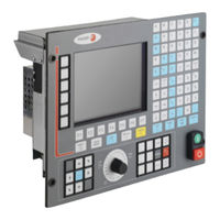
Fagor 8035-M CNC Controller Manuals
Manuals and User Guides for Fagor 8035-M CNC Controller. We have
1
Fagor 8035-M CNC Controller manual available for free PDF download: Installation Manual
Fagor 8035-M Installation Manual (470 pages)
Brand:
Fagor
| Category:
Control Systems
| Size: 3.98 MB
Table of Contents
Table of Contents
5
About the Product
9
Declaration of Conformity
11
Version History (M)
13
Version History (T)
19
Safety Conditions
25
Warranty Terms
29
Material Returning Terms
31
Additional Remarks
33
Fagor Documentation
35
Chapter 1 Cnc Configuration
37
CNC Structure
38
Connectors
40
Chapter 2 Heat Dissipation
57
Heat Dissipation by Natural Convection
58
Heat Dissipation by Forced Convection with Inside Fan
59
Heat Dissipation by Air Flow to the Outside Using a Fan
60
Chapter 3 Machine and Power Connection
61
Digital Inputs and Outputs
64
Analog Inputs and Outputs
65
Setup
66
Connection of the Emergency Input and Output
70
Chapter 4 Machine Parameters
73
Machine Parameters
74
Machine Parameters
75
Parameters that May be Modified from the OEM Program or OEM Subroutine
76
General Machine Parameters
78
Axis Parameters
116
Spindle Parameters
144
Drive Parameters
161
Serial Line Parameters
163
Ethernet Parameters
166
PLC Parameters
170
Tables
173
Leadscrew Error Compensation Table
175
Cross Compensation Parameter Table
177
Chapter 5 Concepts
179
Axes and Coordinate Systems
179
Rotary Axes
182
Gantry Axes
184
Incline Axis
185
Relationship between the Axes and the JOG Keys
187
Movement with an Electronic Handwheel
190
Standard Handwheel
191
Path Handwheel
192
Feed Handwheel Mode
193
Additive Handwheel" Mode
195
Feedback System
197
Axis Adjustment
203
Drive Setting
204
Gain Setting
205
Proportional Gain Setting
206
Feed-Forward Gain Setting
207
Derivative (AC-Forward) Gain Setting
208
Leadscrew Backlash Compensation
209
Leadscrew Error Compensation
210
Reference Systems
212
Home Search
213
Setting on Systems Without Distance-Coded Feedback
216
Setting on Systems with Distance-Coded Feedback
218
Axis Travel Limits (Software Limits)
219
Unidirectional Approach
220
Auxiliary M, S, T Function Transfer
221
Transferring M, S, T Using the AUXEND Signal
223
Spindle Types
225
Spindle Speed (S) Control
226
Spindle Gear Change
228
Spindle in Closed Loop
230
Treatment of Emergency Signals
236
Digital CAN Servo
239
Fagor Handwheels: HBA, HBE and LGB
242
Machine Safety Related Functions
246
Cycle Start Disabled When Hardware Errors Occur
248
Tool Magazine
249
Tool Change Management
250
Gear Ratio Management on Axes and Spindle
251
Example of Axes: Outside Feedback Without Gear Box
252
Example of Axes: Encoder at the Motor
255
Example of Axes: Outside Feedback with Gear Box
256
Example of Spindle: External Encoder Without Gear Box
258
Example of Spindle: Encoder at the Motor
260
Example of Spindle: External Encoder with Gear Box
262
Inputs
265
Outputs
266
Marks
267
Registers
269
Timers
270
Monostable Mode. TG1 Input
273
Delayed Activation Mode. TG2 Input
275
Delayed Deactivation Mode. TG3 Input
277
Signal Limiting Mode. TG4 Input
279
Counters
281
Operating Mode of a Counter
284
CHAPTER 6 PLC Resources
286
Chapter 7 Introduction to the Plc
287
PLC Program Execution
287
Loop Time
290
Modular Structure of the Program
291
First Cycle Module (CY1)
292
Priority of Execution of the PLC Modules
295
Chapter 8 Plc Programming
298
Module Structure
298
Operators and Symbols
305
Action Instruction
306
Binary Assignment Instructions
307
Conditional Binary Action Instructions
308
Sequence Breaking Action Instructions
309
Arithmetic Action Instructions
310
Logic Action Instructions
312
Specific Action Instructions
314
Chapter 9 Cnc-Plc Communication
318
Auxiliary M, S, T Functions
318
Auxiliary M, S, T Function Transfer
321
Transferring M, S, T Using the AUXEND Signal
322
Access to the PLC from the CNC
326
Access to the PLC from a PC, Via DNC
327
Chapter 10 Logic Cnc Inputs and Outputs
330
General Logic Inputs
330
Axis Logic Inputs
338
Spindle Logic Inputs
343
Key Inhibiting Logic Inputs
348
Logic Inputs of the PLC Channel
351
General Logic Outputs
353
Logic Outputs of the Axes
359
Spindle Logic Outputs
361
Logic Outputs of Key Status
363
Chapter 11 Access to Internal Cnc Variables
369
Variables Associated with Tools
369
Variables Associated with Zero Offsets
373
Variables Associated with Machine Parameters
374
Variables Associated with Work Zones
375
Variables Associated with Feedrates
377
Variables Associated with Coordinates
379
Variables Associated with Electronic Handwheels
381
Variables Associated with Feedback
383
Variables Associated with Local and Global Parameters
386
Operating-Mode Related Variables
387
Other Variables
389
Chapter 12 Axes Controlled from the Plc
398
PLC Execution Channel
398
Considerations
399
Blocks Which Can be Executed from the PLC
401
Control of the PLC Program from the CNC
405
Action CNCEX1
407
Chapter 13 Plc Programming Example
410
Definition of Symbols (Mnemonics)
410
First Cycle Module
412
Main Module
413
Advertisement
Advertisement
Related Products
Fagor 8055 M
Fagor 8055 EN
Fagor 8055i M
Fagor 8055i EN
Fagor 8070 BL
Fagor 8070 OL
Fagor 8070 L
Fagor 8035-T
Fagor 8065
Fagor 8060
Fagor Categories
Dishwasher
Refrigerator
Oven
Ventilation Hood
Hob
More Fagor Manuals
Login
Sign In
OR
Sign in with Facebook
Sign in with Google
Upload manual
Upload from disk
Upload from URL