Sign In
Upload
Manuals
Brands
Emerson Manuals
Measuring Instruments
Rosemount Analytical CAT 100
Emerson Rosemount Analytical CAT 100 Manuals
Manuals and User Guides for Emerson Rosemount Analytical CAT 100. We have
1
Emerson Rosemount Analytical CAT 100 manual available for free PDF download: Instruction Manual
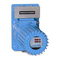
Emerson Rosemount Analytical CAT 100 Instruction Manual (122 pages)
Continuous Analyzer Transmitter
Brand:
Emerson
| Category:
Measuring Instruments
| Size: 2.32 MB
Table of Contents
Table of Contents
3
Preface
9
Intended Use Statement
10
Safety Summary
10
General Precautions for Handling and Storing High Pressure Gas Cylinders
13
Compliances
14
Documentation
14
Definitions
9
1 Description and Specifications
15
Overview
15
Typical Applications
15
Detector Methodologies
16
Non-Dispersive Infrared (NDIR)
16
Figure 1-1. Absorption Bands of Sample Gas and Transmittance of Interference Filters
17
Figure 1-2. Opto-Pneumatic Gas Detector
18
Figure 1-3. Overall NDIR Method
19
Paramagnetic Oxygen Method
20
Figure 1-4. Paramagnetic Oxygen Analysis
20
Electrochemical Oxygen Method
21
Figure 1-5. Electrochemical Oxygen Sensor
21
Figure 1-6. Reaction of Galvanic Cell
22
Thermal Conductivity Method
23
Figure 1-7. Thermal Conductivity Sensor
23
Specifications
25
General
25
CAT 100 Detector
26
2 Installation
27
Process and Calibration Gas Connection
27
Figure 2-1. Gas Connections
28
Figure 2-2. Piping Diagram (Two Channel Series)
29
Figure 2-3. CAT 100 Outline and Mounting Dimensions
30
Gas Conditioning
31
Installation
32
Location
32
Limitations
32
Gas Lines
32
Services
32
Mounting Options
32
Vent Lines
32
Electrical Connections
33
Figure 2-4. Increased Safety Junction Box Terminals
36
Analytical Leak Check
37
Flow Indicator Method
37
Figure 2-5. Leak Check - Flow Indicator Method
37
Manometer Method
38
Figure 2-6. Leak Check - Manometer Method
38
3 Operation
39
Startup Procedure
39
Touchpad
39
Overview
39
Elements
39
Figure 3-1. CAT 100 Touchpad
39
Actuator Tool
40
Operation
40
Figure 3-2. Touchpad Actuator Tool PN 42715575
40
Figure 3-3. Storing the Actuator Tool
40
Functions
41
Figure 3-4. Touchpad Operation
41
Figure 3-5. CAT 100 Analyzer Touchpad Function Identification
41
FUNCTION Touchpad
42
Figure 3-6. CAT 100 Touchpad Functions
42
ENTER Touchpad
43
INPUT-CONTROL Touchpads
43
Figure 3-7. Analyzer Operating Function Matrix
44
Entry of System Parameters
45
Pressure Correction
45
Cross Compensation
45
Cross Compensation Calibration
45
Hold
46
Automatic Calibration
46
Tolerance Check
46
Display off
47
Analog Signal Outputs
47
Flushing Period
47
User Code
47
Response Time
48
Offset Value
48
Range Value
48
Reset
48
Program Version
49
Serial Number
49
Pump
49
Calibration
50
Zeroing
50
Spanning
50
Manual Calibration
51
Zeroing
51
Spanning
51
Automatic Calibration (Option)
53
Zeroing
53
Combined Zeroing and Spanning
53
Concentration Limits
54
Measurement
55
Shut down
56
Temperature Stabilization (Option)
57
Changing Temperature Settings
57
Figure 3-8. Temperature Controller
57
Controller Settings
58
4 Serial Interface Option
61
Overview
61
Protocols
62
Rs 232
63
Rs485
63
Setting Interface Parameters
63
ON/OFF Status
63
Communication Parameters
63
String Syntax
64
Status Strings
65
Numerical Representations
66
Block Parity Check
66
Instruction (Receive) Syntax
67
Instruction Listing
67
Response String Syntax
68
Model CAT
68
5 Maintenance and Service
69
Overview
69
Operating Factors
69
Analyzer Replacement
69
Analyzer Repair
69
Component Removal
70
Figure 5-1. CAT 100 Enclosure Assembly
70
Analyzer Removal
71
Analyzer Replacement
71
Power Supply Assembly Removal
71
Analyzer Configuration and Adjustment
72
Component Layout
72
Figure 5-2. Analyzer Component Layout (Infrared Channel / Oxygen Measurement, Combined)
73
Figure 5-3. Analyzer Component Layout (1 Channel Oxygen Measurement, Electrochemical)
74
Figure 5-4. Analyzer Component Layout (Paramagnetic Oxygen Measurement / Thermal Conductivity, Combined)
75
Photometer Assembly
77
Figure 5-6. Photometer Assembly with Pyroelectrical Detector
78
Figure 5-7. Photometer Assembly with Gas Detector
79
Analyzer Rear Panel
80
Figure 5-8. Analyzer Rear Panel Layout
80
Figure 5-9. Pin Assignments (View Looking at Rear Panel)
81
Thermal Conductivity Response Time
82
Figure 5-10. TC Sensor Short Response Time Setting (Standard)
83
Figure 5-11. TC Sensor Long Response Time Setting
83
Maintenance
84
Routine and Preventive
84
Checking and Cleaning of the Analyzer
84
Cleaning and Replacement of Photometric Components
85
Figure 5-12. Analyzer Photometer Assembly ( 2 Channel Infrared Analyzer, Viewed from Front Panel Side)
85
Light Source Replacement
86
Removal of Analysis Cells
87
Figure 5-13. Photometer Assembly
87
Cleaning of Analysis Cells and Windows
88
Reinstalling Analysis Cells
88
Reinstalling Photometer Assembly
88
Physical Zeroing
88
Replacement of Electrochemical Oxygen Sensor
89
Check of the Sensor
90
Figure 5-14. OXS PCB Measuring Points
90
Removal of the Sensor
91
Figure 5-15. Oxygen Sensor Without Infrared Channel
91
Figure 5-16. OXS PCB Connector P2
92
Figure 5-17. Oxygen Sensor Support (Oxygen Measurement Without Infrared Channel)
92
Figure 5-18. Oxygen Sensor with Infrared Channel
93
Basic Calibration for the Oxygen Sensor
95
Sample Pump Maintenance
95
Figure 5-19. OXS PCB Location of Measuring Points and Voltage Adjustment
95
Replacing the EPROM
96
Figure 5-20. BKS PCB Location of EPROM and Battery Buffer Jumper (J7)
96
Analyzer Service
97
Test Points for BKS PC Board
97
Figure 5-21. BKS PCB Test Points
97
Figure 5-22. BKS PCB Plug Locations
101
Figure 5-23. BKS PCB Jumper Locations
102
Test Points for OXS PC Board
103
Figure 5-24. OXS PCB Test Points
103
Figure 5-25. OXS PCB Plug Locations
104
Power Supply
105
Figure 5-26. Power Supply Connections
105
6 Troubleshooting
107
Error Messages
107
Troubleshooting Leaks
112
7 Return of Material
113
Customer Service
113
Training
113
8 Index
115
Advertisement
Advertisement
Related Products
Emerson CSI 2140
Emerson Clarity II
Emerson Rosemount CT4215
Emerson Rosemount CT5800
Emerson Nelson CM-1
Emerson Rosemount CCO 5500
Emerson Micro Motion CDM100M A Series
Emerson ControlWave Series
Emerson ControlWave EFM
Emerson Rosemount Analytical 400A
Emerson Categories
Controller
Control Unit
Transmitter
Measuring Instruments
Fan
More Emerson Manuals
Login
Sign In
OR
Sign in with Facebook
Sign in with Google
Upload manual
Upload from disk
Upload from URL