Sign In
Upload
Manuals
Brands
Emerson Manuals
Controller
DL8000
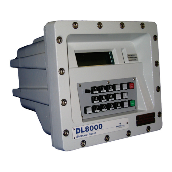
Emerson DL8000 Preset Controller Manuals
Manuals and User Guides for Emerson DL8000 Preset Controller. We have
2
Emerson DL8000 Preset Controller manuals available for free PDF download: Instruction Manual, Safe Use Instructions
Emerson DL8000 Instruction Manual (330 pages)
Preset Controller
Brand:
Emerson
| Category:
Controller
| Size: 11.74 MB
Table of Contents
Table of Contents
3
Contents
3
Wiring
4
Glossary
4
Modbus
4
Communication
5
Chapter 1 - Overview
7
DL8000 Overview
7
Revised February
8
Hardware
9
Housing
9
Revised February
9
Electronics
11
Dial-Up Modem
11
Security Gateway
12
Additional Technical Specifications
12
Chapter 2 - Installation and Use
13
Housing
13
Class I Zone 1 Housing
14
Housing
14
Standard DL8000 Enclosure
14
Securing the Cover to the Class I Zone I Case
16
Class I DIV 2 Housing
17
Card Cage
18
Class I Division 2 DL8000 Housing
18
Backplane
19
Central Processor Unit (CPU)
20
CPU Front View
20
CPU Connectors
21
Ethernet
21
Tab
21
Installing and Removing Wire Channel Covers
22
Removing and Installing Module Covers
23
Removing the CPU Module
23
Installing the CPU Module
24
License Keys
24
License Key
24
Installing a License Key
25
Removing a License Key
26
Installation Planning
27
Mechanical Installation
27
Planning Considerations
28
Electrical Installation
30
General Considerations
30
Field Wiring Installation Guidelines
30
Electrical Wire and Cable Selection and Installation
31
Input/Output Field Signal Wiring
32
Electrical Grounds
32
Wire Conduit Selection and Installation
34
Operator Interface
35
Keypad
36
LED Status Indicators
37
Chapter 3 - Modules
39
Power Input Module
39
Eia-422/485 (Rs-422/485)
39
Volt DC Power Input Module
40
Input/Output Modules
41
Volt DC Power Input Terminal Block
41
I/O
42
General Installation
43
Installing an I/O Module
44
Analog Input (AI) Modules
45
Removing an I/O Module
45
Wiring I/O Modules
45
Analog Output (AO) Modules
47
Analog Output Jumper J4 (Shown Set to +12V)
48
Discrete Input (DI) Modules
48
Field Wiring
48
Pulse Input (PI) Modules
50
Externally Powered Pulse Input Module Field Wiring
51
Discrete Output (DO) Modules
52
DL8000 Powered Pulse Input Module Field Wiring
52
Discrete Output Module Field Wiring
53
Discrete Output Relay (DOR) Modules
53
Discrete Output Relay Module Field
54
Resistance Temperature Detector (RTD) Input Modules
55
Alternating Current Input/Output (AC I/O) Module
56
RTD Sensor Wiring Terminal
56
RTD Wiring
56
Ac I/O
58
Multiple AC I/O Modules
59
Advance Pulse Module (APM)
61
Fuse Wiring with Multiple AC
61
Generic Densitometer Wiring on
62
Series Detector Switch (Normally Closed) Wiring on APM
62
Series Detector Switch (Normally Open) Wiring on APM
62
Independent Detector Wiring on APM
63
Two-Pulse Turbine Pulse Input Wiring on APM
63
Thermocouple (TC) Input Module
65
Thermocouple Input Module Wiring
66
HART® Module
68
Highway Addressable Remote Transducer (HART ® ) Module
68
Communication Modules and Ports
70
HART-2 Module
70
Input Multi-Drop Wiring
70
Output Wiring
70
Built-In Communications and Optional
71
Communication Ports
71
Communication LED Indicator Definitions
72
Wiring Communications
72
Connection
73
Local Operator Interface (LOI - Local Port)
73
Ethernet Communications
74
Using the LOI
74
Module
76
RS-232) Serial Communications
76
Built-In EIA-232 (RS-232) Signal Routing - Comm2
77
Comm5
77
EIA-422/485 (RS-422/485) Serial Communications Module
77
EIA-422/485 (RS-422/485) Jumpers and Termination Resistors
78
Resistors
78
RS-422) Module
78
Dial-Up Modem Communications Module
79
Additional Technical Information
81
Appendix A - Glossary
83
Appendix B - Modbus Communications
93
Modbus Communications
93
Modbus Configuration
94
B.2 Modbus Configuration
94
Modbus Configuration General Tab
95
Modbus Configuration Scale Values Tab
97
Modbus History
99
B.3 Modbus History
99
Modbus Configuration History Table Tab
100
Modbus Events & Alarms Functionality
103
Reading Events & Alarms Register
103
Acknowledging Events & Alarms
103
Modbus Registers
104
B.5 Modbus Registers
104
Modbus Configuration Registers Tab
106
Modbus
109
Modbus Conversion
109
Modbus
110
Modbus Master Table
111
Communications Ports
111
Modbus Configuration Master Table Tab
112
Modbus Master Modem
114
Modbus Configuration Master Modem Tab
114
HMI Information
116
Sequential Blending
116
B.8 HMI Information
116
Ratio Blending
117
Appendix C - Wiring Diagrams
119
Daniel Senior Sonic Meter to PI Module
119
Daniel 1818A and 1838 Turbine Pre-Amp to PI Module
120
Micro Motion RFT9739 & 2400S Transmitters to PI Module
121
Micro Motion 2400S Transmitter
121
Micro Motion RFT9739 & 2400S Transmitters to APM Module
122
Micro Motion RFT9739 Transmitter
122
3- and 4-Wire RTD to RTD Module
123
Daniel Senior Sonic Meter to APM Module
124
Daniel 1818A and 1838 Dual Turbine Pre-Amp to APM Module
125
Daniel 1818A and 1838 Turbine Pre-Amp to APM Module
126
Two-Stage Valve with Two Limit Switches to APM Module
127
Two-Stage Valve
127
Micro Motion 1700 & 2700 Transmitter to PI Module
128
Appendix D - Communications Protocols
129
Introduction
129
Danload 6000
129
Communication Channels
130
Communications Failure
130
Mapping Modbus Registers
131
Modbus Protocol
131
Supported Protocols
131
Configuration
133
Commands
134
I/O Module
134
Modbus
134
Status Flags
135
Batch Control in Auto Mode
136
Steps for Authorizing a Transaction
136
Steps for Authorizing a Batch
139
Stop/End of Batch
140
End of Transaction
141
Batching Status States
142
Sequential Blending
142
Communications Commands
143
Modbus Commands
143
D.3 Communications Commands
143
Prompt Recipe (0X01)
144
Prompt Additives (0X03)
145
Timeout Operation (0X05)
146
Authorize Batch (0X0A
149
Stop Batch (0X0F)
152
Danload 6000 Protocol Commands
158
Exception Codes
160
Authorize Transaction (0X06
163
Prompt Preset Volume (0X08)
165
Start/Restart Batch (0X0E)
170
Additive Totalizer (0X11
172
Meter Totalizers (0X15)
175
Unauthorized Flow (0X17)
176
Transaction Data by Component (0X1F)
182
Initialize Transaction Storage (0X20)
184
Start Communication (0X21)
184
Set Program Code Value (0X23)
186
Get Date and Time (0X28)
188
Last Key Pressed (0X31)
189
Swing Arm Side (0X33)
189
Mapping Modbus Registers
201
Modbus Registers
201
Danload 6000 Protocol Frame
204
BCC Calculation
205
D.6 BCC Calculation
205
Checksum Table
206
D.7 CRC-16 Checksum Table
206
Status Flags Description [63,0,119
208
Status Flags
208
D.8 Status Flags Description [63,0,119]
208
Exception Codes
213
D.9 Exception Codes
213
New/Unused Danload 6000 Exception Codes
215
Alarm Logs
216
Meter Factor
216
Error Codes
218
Appendix E - DL8000 Keypad Display
219
Keypad Display Components
219
Keypad
219
DL8000 Keypad
219
E.1.1 Keypad
220
LED Status Indicators
222
Liquid Crystal Display (LCD
223
Power Failure
223
Operational Modes
224
Loading Mode
224
Recipe Selection
224
Invalid Recipe Selection
225
Additive Selection
225
Data Item Prompt
225
Messages
225
Preset Quantity
226
Invalid Preset
226
Loading
226
Transaction End Prompt
228
Conditional String Display for Temperature Correction String
228
Program Mode
230
ROCLINK 800 Configuration
230
E.3 Program Mode
230
Log in
231
Initial Menu
232
E.3.5 Select Language
233
E.3.7 Display Setting
234
Alarm
236
Apm
239
E.3.9 Setup/ Configuration
240
Clear Alarms
263
Print Record
263
Current Status
263
Generic TLP for Setup and Status
263
Calibration
263
E.3.11 Online Help
265
E.4 Calibration
267
Calibrating Additive Meters
268
Calibrating Analog Input
271
Calibrating Rtds
273
Rtd
275
Calibrating Product Meters
277
Diagnostics
293
Diagnosing Digital Outputs (DO
293
E.5 Diagnostics
293
Diagnosing Digital Inputs (DI
296
Diagnosing Analog Outputs (AO
299
Diagnosing Analog Inputs (AI
303
Diagnosing AC Input/Outputs (AC I/O
307
DIP Switches
307
Diagnosing RS-232 Communication Ports
311
Diagnosing RS-485 Communication Ports
313
RS-485) Module
315
Error Messages
318
Translated Alarm and Status Messages
319
Setup/Configuration
321
Index
323
Advertisement
Emerson DL8000 Safe Use Instructions (66 pages)
Preset Controller
Brand:
Emerson
| Category:
Controller
| Size: 3.1 MB
Table of Contents
Installation
5
Einbau
13
Installazione
45
Instalación
61
Cableado de Alimentación
62
Advertisement
Related Products
Emerson FISHER FIELDVUE DLC3010
Emerson Fisher FIELDVUE DLC3020f
Emerson FIELDVUE DVC6200f
Emerson Fisher FIELDVUE DVC6000 HW2
Emerson Fisher FIELDVUE DVC6000
Emerson Double-Acting Series
Emerson D150
Emerson D100
Emerson D1600
Emerson Fisher Fieldvue DVC6030f
Emerson Categories
Controller
Control Unit
Transmitter
Measuring Instruments
Fan
More Emerson Manuals
Login
Sign In
OR
Sign in with Facebook
Sign in with Google
Upload manual
Upload from disk
Upload from URL