Sign In
Upload
Manuals
Brands
Emerson Manuals
Power Supply
ACTURA Flex 48330
Emerson ACTURA Flex 48330 Manuals
Manuals and User Guides for Emerson ACTURA Flex 48330. We have
1
Emerson ACTURA Flex 48330 manual available for free PDF download: User Manual
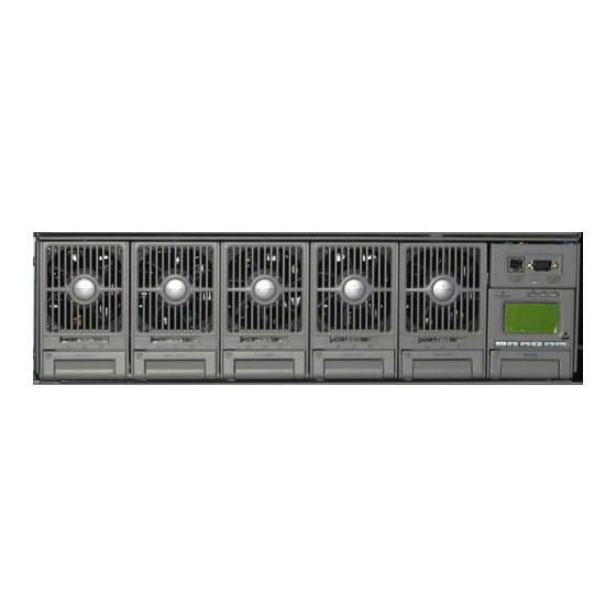
Emerson ACTURA Flex 48330 User Manual (96 pages)
Power System
Brand:
Emerson
| Category:
Power Supply
| Size: 2.21 MB
Table of Contents
User Manual
1
Table of Contents
5
Chapter 1 System Description
11
Abbreviation
11
Introduction
11
Features
11
System Configuration
12
Figure 1-1 Outline
12
Table 1-1 Configurations of Actura Flex 48330 Power System
13
Components
14
Rectifier Shelf
14
Figure 1-2 Rectifier Shelf Outline
14
Figure 1-3 Rectifier Shelf with Rectifiers and CU
14
Table 1-2 Dimensions of Rectifier Shelf
15
Rectifier
16
Figure 1-4 Dimensions
16
Scu
17
Table 1-3 Function of Indicators
17
Figure 1-5 Outline of SCU
17
Multi-Function Unit (MFU)
19
Table 1-4 Authority and Default Password
19
Figure 1-6 Outline and Components of MFU
19
Battery Connection Unit (BCU)
20
Table 1-5 Configuration of MFU
20
Figure 1-7 Outline of Battery Connection Unit (BCU)
20
System Cabinet
21
Table 1-6 BCU Configuration
21
Chapter 2 Installation
22
Installation Preparation
22
Environmental Conditions
22
Power Supply
22
Table 2-1 Environmental Conditions in Power Room
22
Site Survey
23
Tools & Material
23
Unpacking
24
Installation Procedures
25
Cabinet Installation
25
Figure 2-1 Installation Dimensions of the Cabinet Base
25
Figure 2-2 Installing Expansive Pipe
26
Figure 2-3 Fixing Cabinet with Tap
26
External Electrical Connection Interface
27
Connection of Input Cables
27
Table 2-2 AC Input Modes
27
Figure 2-4 Cable Mounted with H Terminal
27
Figure 2-5 Connection of Input Terminals
28
Figure 2-6 Top Cover
28
Figure 2-7 Connection of 3-Phase AC Power Input
28
Figure 2-8 Connection of Single-Phase AC Power Input
29
Figure 2-9 Connection of Dual-Phase AC Power Input
29
Connection of Load Cables
30
Table 2-3 Configuration Number of Load Mcbs and Battery Mcbs
30
Figure 2-10 Connection of Load Cables
30
Figure 2-11 Cable Connection to MCB
30
Connection of Communication Cables
31
Figure 2-12 Connector Board in Rectifier Shelf
31
Layout of Connector Board S6415X2
32
Figure 2-13 Layout of Connector Board S6415X2
32
Interface Definition of Connector Board S6415X2
33
Table 2-4 Interface Definition of Connector Board S6415X2
33
Connection of Temperature Sensor Cables
34
Connection with MODEM
34
Figure 2-14 Input/Output Interfaces of TD-5648DC MODEM
34
Connection with Dry Contacts
35
Battery Installation and Cabling
35
Battery Installation
35
Battery Cable Connection
36
Figure 2-15 Cabinet with Four Battery Strings Installed
36
Figure 2-16 Connection of Battery Cables
37
Figure 2-17 Positive and Negative Battery Cables in each Level
37
Figure 2-18 Negative Battery Cables Connection in BCU
38
Parallel Connection of Cabinets
39
Figure 2-19 Parallel Connection of DC Power System Cabinet with Battery Cabinet
39
Chapter 3 Startup
40
Checking before Startup
40
Table 3-1 System Checklist before Startup
40
Startup Process
41
Parameters Configuration
41
Chapter 4 Testing
42
Testing MFU
42
Testing Rectifier
42
Testing SCU
42
Battery Breaker Test
43
BCU Test
43
Load Breaker Test
43
Chapter 5 Operating SCU
44
Operation Panel
44
Table 5-1 Functions of LED Indicators
44
Table 5-2 Functions of SCU Keys
44
Figure 5-1 SCU Front Panel
44
Operation Procedures
45
Querying System Status
46
First Page of System Information
46
Other System Information Screen
47
Querying Rectifier Status
49
Querying Alarms and Setting Alarm Plans
50
Querying Active Alarm
50
Query Alarm History
51
Alarm Type Table
53
Table 5-3 Alarm Type Table
53
Changing Audible/Visual Alarm and Alarm Call Back Plan
56
Changing Alarm Types of Dry Contacts
56
Setting Alarm Type for Dry Contacts
56
Table 5-4 Changing Audible/Visual Alarm and Alarm Call Back Plan
56
Table 5-5 Optional Alarm Types
57
Set the Alarm Names through PLC Function
58
Table 5-6 Logic Matrix Used for Configuring 8 Dry Contacts
59
Table 5-7 Example of PLC Setting
59
Table 5-8 PLC SN and Alarm
59
Maintenance
61
Setting System Parameters
63
Parameter Setting Method
63
Table 5-9 Password Levels and Authorities
64
Batt. Selection
65
LVD Parameter Description
66
Table 5-10 Value Description of the Basic Battery Parameters
66
Charging Management Parameters
67
Table 5-11 Value Description of the LVD Parameters
67
Table 5-12 Charging Management Parameter Value Description
69
Figure 5-2 BC/FC Switchover Diagram
69
Battery Test Parameters
70
Table 5-13 Value Description of the Battery Test Parameters
71
Figure 5-3 Schematic Diagram of the Test Function
71
Temperature Compensation Coefficient Parameters
72
Table 5-14 Value Description of Temperature Compensation Coefficient
72
AC Settings
73
Table 5-15 Value Description of AC Settings
73
DC Setting
74
Table 5-16 Value Description of DC Settings
74
Rect Settings
75
Table 5-17 Value Description of Rectifier Settings
75
System Settings
76
Table 5-18 Value Description of System Settings
78
Figure 5-4 System Model Description
79
Alarm Settings
80
Table 5-19 Relationship between System Model and System Type
80
Table 5-20 Value Description of Alarm Settings
81
Chapter 6 Routine Maintenance
82
Maintenance of Rectifier
82
Maintenance of SCU
82
Maintenance of MFU
82
Cover Plates
83
Battery Maintenance
83
Storage and Supplementary
83
Daily Inspection
83
Replacement
84
Chapter 7 Troubleshooting
85
Troubleshooting Rectifier
85
Table 7-1 Troubleshooting
85
Mains Failure
86
Disastrous Accidents
86
Appendix 1 System Technical Parameters
87
Appendix 2 Engineering Design Diagram
89
Appendix 2.1 Engineering Design Diagram for 2000Mm%600Mm%600Mm Cabinet
89
Appendix 2.2 Engineering Design Diagram for 2000Mm%600Mm%400Mm Cabinet
90
Appendix 2.3 Engineering Design Diagram for 700Mm%600Mm%400Mm Cabinet
91
Appendix 2.4 System Input and Output Connector Specs
91
Appendix 3 System Circuit Diagram
92
Appendix 3.1 System Electric Schematic Diagram
92
Appendix 3.2 System Wiring Diagram
93
Appendix 3.3 MFU Electric Wiring Diagram
94
Appendix 3.4 BCU Electric Wiring Diagram
95
Appendix 4 Glossary
96
Advertisement
Advertisement
Related Products
Emerson FL
Emerson COPELAND FLCNA-ZF15-TFM
Emerson COPELAND FLD8A-ZF 06-TFM
Emerson COPELAND FLH8A-ZF 11-TFM
Emerson COPELAND FLR6A-ZF 15-TFM
Emerson COPELAND FLR7A-ZF 18-TFM
Emerson COPELAND FLV9A-ZF 34-TFM
Emerson COPELAND FLV6A-ZF 34-TFM
Emerson COPELAND FLS9A-ZF18-TF7
Emerson 101-132-2075
Emerson Categories
Controller
Control Unit
Transmitter
Measuring Instruments
Fan
More Emerson Manuals
Login
Sign In
OR
Sign in with Facebook
Sign in with Google
Upload manual
Upload from disk
Upload from URL