Sign In
Upload
Manuals
Brands
Element 14 Manuals
Motherboard
BeagleBone Black INDUSTRIAL
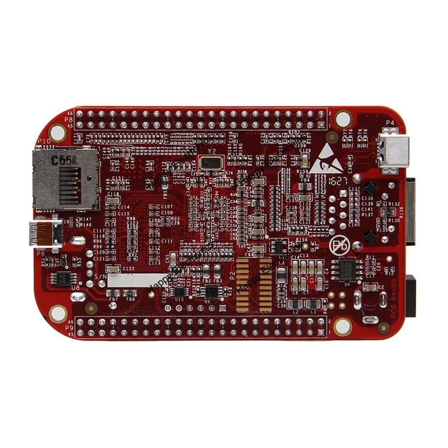
Element 14 BeagleBone Black INDUSTRIAL Manuals
Manuals and User Guides for Element 14 BeagleBone Black INDUSTRIAL. We have
1
Element 14 BeagleBone Black INDUSTRIAL manual available for free PDF download: User Manual
Element 14 BeagleBone Black INDUSTRIAL User Manual (118 pages)
Brand:
Element 14
| Category:
Motherboard
| Size: 23.3 MB
Table of Contents
Table of Contents
7
1 Introduction
12
2 Change History
12
Board Changes
12
3 Connecting up Your Element14 Beaglebone Black Industrial
12
What's in the Box
13
Main Connection Scenarios
13
Figure 1 Kit Contents
13
Tethered to a PC
14
Figure 2 Tethered Configuration
14
Figure 3 Usb Connection to the Board
15
Figure 4 Board Power Led
15
Figure 5 Board Boot Status
16
Standalone W/Display and Keyboard/Mouse
17
Figure 6 Desktop Configuration
17
Figure 7 Connect Microhdmi Cable to the Monitor
18
Figure 8 DVI-D to Hdmi Adapter
18
Figure 9 Wireless Keyboard and Mouse Combo
18
Figure 10 Connect Keyboard and Mouse Receiver to the Board
19
Figure 11 Keyboard and Mouse Hubs
19
Figure 12 Ethernet Cable Connection
20
Figure 13 External DC Power
20
Figure 14 Connect Microhdmi Cable to the Board
21
Figure 15 Board Boot Status
21
Figure 16 Desktop Screen
22
4 Element14 Beaglebone Black Industrial Overview
23
Beaglebone Compatibility
24
Element14 Beaglebone Black Industrial Features and Specification
25
Table 1 Element14 Beaglebone Black Industrial Features
25
Board Component Locations
26
Figure 17 Connectors, Leds and Switches
26
Figure 18 Key Components
27
5 Element 14 Beagle Bone Black Industrial High Level Specification
28
Block Diagram
28
Processor
28
Figure 19 Element14 Beaglebone Black Industrial Key Components
28
Memory
29
Power Management
30
PC USB Interface
31
Serial Debug Port
31
USB1 Host Port
31
Power Sources
31
Reset Button
32
Power Button
32
Indicators
32
CTI JTAG Header
33
HDMI Interface
33
Cape Board Support
33
6 Detailed Hardware Design
34
Figure 20 Element14 Beaglebone Black Industrial Block Diagram
34
Power Section
35
Tps65217C Pmic
35
Figure 21 High Level Power Block Diagram
35
DC Input
37
Figure 22 Tps65217C Block Diagram
37
USB Power
38
Figure 23 Tps65217 DC Connection
38
Power Selection
39
Figure 24 Usb Power Connections
39
Power Button
40
Battery Access Pads
40
Table 2 Element14 Beaglebone Black Industrial Battery Pins
40
Power Consumption
41
Processor Interfaces
41
Table 3 Element14 Beaglebone Black Industrial Power Consumption (Ma@5V)
41
Power Rails
42
Figure 25 Power Rails
43
Figure 26 Power Rail Power up Sequencing
45
Figure 27 Tps65217C Power Sequencing Timing
45
Power LED
46
TPS65217C Power up Process
46
Figure 28 Power Processor Interfaces
46
Processor Control Interface
47
Low Power Mode Support
47
Sitara Am3358Bzcza100 Processor
48
Description
48
Figure 29 Sitara Am3358Bzcz Block Diagram
48
High Level Features
49
Documentation
49
Table 4 Processor Features
49
Crystal Circuitry
50
Reset Circuitry
50
Figure 30 Processor Crystals
50
Memory Device
51
Figure 31 Board Reset Circuitry
51
DDR3L Memory Design
52
Figure 32 Ddr3L Memory Design
53
Power Rails
54
Vref
54
Figure 33 Ddr3L Vref Design
54
4Gb Emmc Memory
55
Emmc Device
55
Emmc Circuit Design
55
Figure 34 Emmc Memory Design
56
Table 5 Emmc Boot Pins
56
Board ID Eeprom
57
Figure 35 Eeprom Design Rev A5
57
Table 6 Eeprom Contents
57
Micro Secure Digital
58
Microsd Design
58
Figure 36 Microsd Design
58
User Leds
59
Figure 37 User Leds
59
Table 7 User Led Control Signals/Pins
59
Boot Configuration
60
Boot Configuration Design
60
Figure 38 Processor Boot Configuration Design
60
Default Boot Options
61
10/100 Ethernet
61
Figure 39 Processor Boot Configuration
61
Ethernet Processor Interface
62
Figure 40 Ethernet Processor Interface
62
Ethernet Connector Interface
63
Figure 41 Ethernet Connector Interface
63
Ethernet PHY Power, Reset, and Clocks
64
Figure 42 Ethernet. Phy, Power, Reset and Clocks
64
LAN8710A Mode Pins
65
Figure 43 Ethernet Phy Mode Pins
65
Hdmi Interface
66
Supported Resolutions
66
Table 8 Hdmi Supported Monitor Resolutions
66
HDMI Framer
67
HDMI Video Processor Interface
67
HDMI Control Processor Interface
68
Interrupt Signal
68
Figure 44 Hdmi Framer Processor Interface
68
Table 9 Tda19988 I2C Address
68
Audio Interface
69
Figure 45 24.576Mhz Oscillator
69
Power Connections
70
HDMI Connector Interface
70
Figure 46 Hdmi Power Connections
70
Figure 47 Connector Interface Circuitry
71
Usb Host
72
Power Switch
72
ESD Protection
72
Filter Options
72
Figure 48 Usb Host Circuitry
72
Pru-Icss
73
PRU-ICSS Features
73
PRU-ICSS Block Diagram
73
Figure 49 Pru-Icss Block Diagram
73
PRU-ICSS Pin Access
74
Table 10 Pru0 and Pru1 Access
74
7 Connectors
75
Expansion Connectors
75
Figure 50 Expansion Connector Location
75
Table 11 Expansion Header P8 Pinout
77
Table 12 Expansion Header P9 Pinout
79
Power Jack
80
Figure 51 5Vdc Power Jack
80
USB Client
81
Figure 52 Usb Client Connector
81
USB Host
82
Figure 53 Usb Host Connector
82
Serial Header
83
Figure 54 Serial Debug Header
83
Figure 55 Ftdi Usb to Serial Adapter
84
Figure 56 Serial Connector
84
Table 13 J1 Serial Header Pins
84
Hdmi
86
Figure 57 Hdmi Connector
86
Figure 58 Hdmi Cable
86
Microsd
87
Figure 59 Microsd Connector
87
Ethernet
88
JTAG Connector
88
Figure 60 Ethernet Connector
88
8 Cape Board Support
89
Element14 Beaglebone Black Industrial Cape Compatibility
90
Table 14 P8 Lcd Conflict Pins
90
Table 15 P8 Emmc Conflict Pins
91
Eeprom
92
Figure 61 Expansion Board Eeprom Without Write Protect
93
Figure 62 Expansion Board Eeprom Write Protect
94
Table 16 Expansion Board Eeprom
94
Table 17 Eeprom Pin Usage
97
Pin Usage Consideration
99
Figure 63 Expansion Boot Pins
99
Expansion Connectors
100
Figure 64 Single Expansion Connector
100
Figure 65 Single Cape Expansion Connector
101
Table 18 Single Cape Connectors
101
Figure 66 Expansion Connector
102
Figure 67 Stacked Cape Expansion Connector
102
Table 19 Stacked Cape Connectors
102
Figure 68 Stacked W/Signal Stealing Expansion Connector
103
Signal Usage
104
Figure 69 Connector Pin Insertion Depth
104
Cape Power
106
Table 20 Expansion Voltages
106
Mechanical
107
Figure 70 Cape Board Dimensions
108
9 Element14 Beaglebone Black Industrial Mechanical
110
Dimensions and Weight
110
Silkscreen and Component Locations
110
Figure 71 Board Dimensions
110
Figure 72 Component Side Silkscreen
111
Figure 73 Circuit Side Silkscreen
112
10 Pictures
113
Figure 74 Top Side
113
11 Support Information
114
Hardware Design
114
Figure 75 Bottom Side
114
Software Updates
115
RMA Support
116
Figure 76 Serial Number Location
116
Figure 78 Serial Number Format
116
Trouble Shooting HDMI Issues
117
Advertisement
Advertisement
Related Products
Element 14 BBONE-BLACK-IND-4G
Element 14 Raspberry Pi
Element 14 Categories
Motherboard
Computer Accessories
Set-top boxes
Desktop
More Element 14 Manuals
Login
Sign In
OR
Sign in with Facebook
Sign in with Google
Upload manual
Upload from disk
Upload from URL