Sign In
Upload
Manuals
Brands
ELCOM Manuals
Cash Register
Euro-500 Handy Series
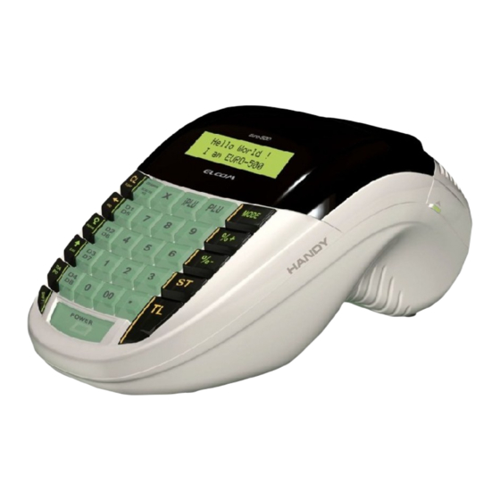
ELCOM Euro-500 Handy Series Manuals
Manuals and User Guides for ELCOM Euro-500 Handy Series. We have
1
ELCOM Euro-500 Handy Series manual available for free PDF download: Service Manual
ELCOM Euro-500 Handy Series Service Manual (80 pages)
Brand:
ELCOM
| Category:
Cash Register
| Size: 7.44 MB
Table of Contents
Table of Contents
3
1 Introduction
9
Euro-500TX Handy Technical Parameters
9
System Configuration
9
Block Chart of ECR Euro-500TX
9
Fig. 1.1: Block Chart of ECR Euro-500TX
9
2 Circuit Schemes and Functions
10
Power Supply Circuits
10
External Power Supply
10
Primary Power Supply
10
The +5 V Power Source (VCC) and the NMI Signal Generator
10
Fig. 2.1 Primary Power Supply
10
Fig. 2.2 +5 V Power Supply and the NMI Signal Generator
10
The +5 V Power Source (VCC1)
11
Power Supply for the Printer Performance Circuits (VH)
11
Accumulator Voltage to the VH Voltage Converter
11
Fig. 2.3 VCC1 Power Supply
11
Fig. 2.4 VH Power Supply
11
Fig. 2.5 Accumulator Voltage Converter Circuit
11
Nimh Accumulator Charging Circuit
12
Fiscal Memory Power Supply Circuits
12
Power Supply Voltages Characteristics
12
Fig. 2.6 Nimh Accumulator Charging Circuit
12
Fig. 2.7 FM Power Supply Circuits
12
The Microcontroller and Its Support Circuits
13
The E-500TXN Microcontroller
13
Fig. 2.8 the E-500TXN Microcontroller
13
Tab. 2.1 Description of the E-500TXN Microcontroller Signals
13
Memory Circuits
15
Fig. 2.9 Memory Connexion
15
Start-Up and Turning off of the System
16
Real-Time Circuit
16
Fig. 2.10 Reset Controller
16
Fig. 2.11 Standby Controller
16
Fig. 2.12 Real-Time Circuit
16
I/O Circuits
17
Printing Control Circuits
17
Fig. 2.13 Printer Control Signals
17
Fig. 2.14 Printer Motor Control and Control of the Journal Winding Motor
17
Keyboard
18
Fig. 2.15 Journal Winding Motor Connexion
18
Fig. 2.16 Receipt Paper Tape Detection in the Printer
18
Fig. 2.17 Journal Paper Tape Detection in the Printer
18
Fig. 2.18 Measuring the Printer Head Temperature
18
Fig. 2.19 Detecting the Printer Head Position
18
Fig. 2.20 Connectors for Fitting the Interconnect PCB
18
Tab. 2.2 Winding Motor Connexion
18
Fig. 2.21 Keyboard Connexion Scheme
19
Fig. 2.22 Signal Chart on the 7442 Decoder (Outlets a - C)
19
Fig. 2.23 Signal Chart on the 7442 Decoder (Outlets 0 - 7)
19
Displays
20
Fig. 2.24 the Display Control in the Euro-500TX Handy
20
Communication Circuits
21
Fig. 2.25 Segment LCD and the NJU6432B Display Controller Connexion
21
Fig. 2.26 NJU6432B Display Controller Connexion
21
Fig. 2.27 View on the Display Placement in Euro-500TX Handy
22
Fig. 2.28 View on the Display Placement in Greek Version of Euro-500TX Handy
22
Fig. 2.29 Communication Circuits and the External PC Keyboard Interface
23
Connexion of Fiscal Memory Circuits
24
Fig. 2.30 Connectors for Fitting the Connectors PCB
24
Fig. 2.31 FM Connexion
24
Other Circuits
25
Fig. 2.32 Power Supply Voltage Checking Circuits
25
Fig. 2.33 Buzzer Circuit
25
Fig. 2.34 Drawer Opening Circuit and the Opening Signal Chart
25
Fig. 2.35 the Circuit Reading the Keyboard and Jumpers' Status
25
Fig. 2.36 Individual ECR Connectors Pin Connexion
26
Fig. 2.37 Connector PCB Connexion
26
3 Thermal Printer LT1320
27
Basic Specification
27
Thermal Head
27
Thermal Head Composition
27
Fig. 3.1 Thermal Head Connexion
27
Data Processing in the Printing Head
28
Printing Data and Their Position
28
Thermistor Specification
28
Time Diagram
28
Fig. 3.2 Printing Data Placement
28
Fig. 3.3 Time Diagram
28
Tab. 3.1 Gates (Strobes) Placement
28
Paper Feeding
29
Step-Motor Specification
29
Excitation Sequence
29
Control Circuit
29
Fig. 3.4 Performance Signals of the Step-Motor
29
Fig. 3.5 Control Circuit
29
Tab. 3.2 Step-Motor Specification
29
Tab. 3.3 Excitation Sequence Signals
29
Printing Head Position Sensor
30
Paper Tape Presence Detectors
30
Overall Time Diagram
30
Fig. 3.6 Outer Part of the Head Position Sensor
30
Fig. 3.7 Sensor Circuit on the Main PCB
30
Fig. 3.8 External Sensor Circuit on the Interconnect PCB
30
Fig. 3.9 Overall Time Diagram
30
Printer Connectors
31
Printing Head Connectors
31
Fig. 3.10 Placement of Thermal Head Connector
31
Tab. 3.4 Connector Types Placed on the Printer
31
Tab. 3.5 Thermal Head Connector Pin Description
31
Terminal for the Sensors
32
Cleaning of the Printing Head
32
Fig. 3.11 Sensor Connexion to the Connector
32
Tab. 3.6 Sensor Terminal Pin Description
32
4 Reinstallation of Individual Modules
33
ECR Disassembly
33
Fig. 4.1 Rough ECR Cover Disassembly Chart
33
Tab. 4.1 Table of Shown Parts
33
Fig. 4.2 Releasing of the Keyboard
34
Fig. 4.3 Pulling out the Middle Cover
34
Reinstallation of Accumulator
35
Printer Reinstallation
35
Fig. 4.4 Fixation and Localisation of the Accumulators
35
Tab. 4.2 Table of Shown Parts
35
Fig. 4.5 Printer Reinstallation at Segment LCD
36
Tab. 4.3 Table of Shown Parts
36
Fig. 4.6 Printer Reinstallation at Alphanumerical LCD
37
Tab. 4.4 Table of Shown Parts
37
Motor Reinstallation
38
Fig. 4.7 Motor Reinstallation
38
Fig. 4.8 Bottom View of Motor Cover
38
Tab. 4.5 Table of Shown Parts
38
Reinstallation of the Main PCB
39
EPROM Reinstallation
39
Fig. 4.9 Fitting of the Main PCB
39
Tab. 4.6 Table of Shown Parts
39
Defective SRAM Replacement or Replacing the SRAM to Higher Capacity
40
Fig. 4.10 EPROM Chip on the Main PCB
40
Tab. 4.7 Table of Shown Parts
40
Nicd Accumulator Reinstallation
41
Reinstallation of the Keyboard or Individual Keys
41
Fig. 4.11 Nicd Accumulator on the Main PCB
41
Tab. 4.8 Table of Shown Parts
41
Fig. 4.12 Keyboard Disassembly
42
Fig. 4.13 Individual Keyboard Keys
42
Tab. 4.9 Table of Shown Parts
42
Reinstallation of Displays
43
Reinstallation of Displays for the ECR Euro-500TX Handy
43
Fig. 4.14 Display Reinstallation
43
Tab. 4.10 Table of Shown Parts
43
Reinstallation of Displays for the Greek Version of Euro-500TX Handy
44
Fig. 4.15 Display Reinstallation in the Greek Version of Euro-500TX Handy
44
Tab. 4.11 Table of Shown Parts
44
ECR Connectors
45
Connectors Placed on the Main PCB
45
Connector for External Devices
45
Fig. 4.16 ECR Connectors
45
Fig. 4.17 Connectors PCB Placement
45
Segment LCD Backlight Installation
46
Connection of the External ECR Drawer
46
Fig. 4.18 Segment LCD Backlight Installation
46
Fig. 4.19 Overlay for PCB for the LCD with Backlight
46
Tab. 4.12 Table of Shown Parts
46
Fig. 4.20 Connection of the External ECR Drawer
47
Fig. 4.21 Modular Jack 4×4 Connexion
47
Connection of the External Keyboard
48
Connection of Euro-500TX Handy to the PC Using the RS-232 Interface
48
Fig. 4.22 Connection of the External Keyboard
48
Fig. 4.23 Mini DIN PS/2 Connector
48
Fig. 4.24 PC Communication Cable Connexion
48
Scanner and Scales Connection to the Euro-500TX Handy Via the RS-232 Interface
49
Fig. 4.25 Scanner/Scales Communication Cable Connexion
49
Tab. 4.13 Pin Connexion for the Scanner
49
Tab. 4.14 Pin Connexion for the Scales
49
5 ECR Tests
50
Display Tests
50
Fig. 5.1 the Segment LCD Area Division
50
Tab. 5.1 the ECR Euro-500TX Handy Tests
50
Printer Tests
51
Printing Test
51
Thermal Head Position Test
51
Paper Presence Sensor Test
51
Keyboard Tests
52
Keyboard Test 1
52
Keyboard Test 2
52
Fig. 5.2 the Keyboard Keys Arrangement
52
Communication Interfaces Tests
53
RS-232 Serial Interface Test for PC
53
Fig. 5.3 the Correct Sequence for Pressing the Keys at Keyboard Test 2
53
Fig. 5.4 Modular Jack 6×6 Terminal Connector
53
RS-232 Serial Interface Test for Scanner and Scales
54
External PC Keyboard Interface Test
54
Fig. 5.5 Mini DIN PS/2 Terminal Connector
54
ECR Drawer Test
55
Fiscal Memory Tests
55
FM Data Reading Tests
55
Tab. 5.2 FM Partitioning for Individual Tests
55
FM Data Writing Tests
56
FM Working Voltages Test
56
FM Control Signals Test 1
56
FM Control Signals Test 2
57
EPROM Checksum Test
57
Accumulator Tests
57
Accumulator Status Test
57
VCC1 Power Supply Test
58
6 Troubleshooting
59
Power Supply Troubleshooting
59
Microprocessor Troubleshooting
60
Printing Troubleshooting
61
Display Troubleshooting
63
Keyboard Troubleshooting
63
Communication Troubleshooting
64
Real-Time and Date Troubleshooting
64
Miscellaneous Troubleshooting
64
7 Ordering and Listing of Spare Parts
66
ECR Parts Classification
66
Arrangement and Listing of Main PCB Parts
66
Fig. 7.1 Main PCB Top Overlay
66
Fig. 7.2 Main PCB Bottom Overlay
67
Tab. 7.1 Bill of Material for the Main PCB
67
Arrangement and Listing of Keyboard Parts
75
Fig. 7.3 Keyboard PCB Top Overlay
75
Arrangement and Listing of Segment LCD Module
76
Fig. 7.4 Segment LCD Module Top and Bottom Overlay
76
Tab. 7.2 Bill of Material for the Keyboard PCB
76
Tab. 7.3 Bill of Material for the Segment LCD Module
76
Arrangement and Listing of Connectors PCB
77
Arrangement and Listing of Interconnecting PCB
77
Fig. 7.5 Connectors PCB Overlay
77
Fig. 7.6 Intercon PCB Top and Bottom Overlay
77
Tab. 7.4 Bill of Material for the Connectors PCB
77
Tab. 7.5 Bill of Material for the Intercon PCB
78
Advertisement
Advertisement
Related Products
ELCOM Euro-500TE
ELCOM Euro-50T Mini
Elcom Euro-500T Handy
ELCOM Euro-50TE Mini
ELCOM Euro-50iTE Mini
ELCOM Euro-50
Elcom Euro-200TE
Elcom Euro-200TX
ELCOM Euro-2500TX
ELCOM Euro-2500 Series
ELCOM Categories
Cash Register
Intercom System
Touch terminals
Desktop
Industrial Equipment
More ELCOM Manuals
Login
Sign In
OR
Sign in with Facebook
Sign in with Google
Upload manual
Upload from disk
Upload from URL