Sign In
Upload
Manuals
Brands
EDMI Manuals
Measuring Instruments
Atlas Mk7
EDMI Atlas Mk7 Manuals
Manuals and User Guides for EDMI Atlas Mk7. We have
1
EDMI Atlas Mk7 manual available for free PDF download: Hardware Reference Manual
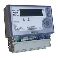
EDMI Atlas Mk7 Hardware Reference Manual (112 pages)
Energy Meters
Brand:
EDMI
| Category:
Measuring Instruments
| Size: 2.78 MB
Table of Contents
Table of Contents
3
Chapter 1 Introduction
9
Using this Manual
9
Conventions Used in this Manual
9
For more Information
10
Chapter 2 The Mk10 Meter
11
Dimensions and Mounting
11
Figure 2-1 Overall Dimensions of the Meter
11
Figure 2-2 Mounting Points, Standard Terminal Cover
12
External Features
14
Under the Terminal Cover
15
Special I/O Variant
16
Table 2-1 Terminal Block Connections
16
Mk10A Variant
17
Table 2-2 Special I/O Terminal Block Connections
17
UPS Variant
18
Table 2-3 Mk10A Terminal Block Connections
18
Terminal Spacing
19
Ups Terminal Block Connections
19
New Terminal Block
20
Finger Guard
20
Terminal Cover Tamper Detect
20
Table 2-5 Terminal Sizes
20
Meter Lid Tamper Detect
21
Under the Meter Lid
21
CT to VT Links
21
Config Jumper
23
Connections in Detail
24
Current and Voltage
24
Mk10 Serial Port Configurations
25
Table 2-6 Mk10 Serial Port Options
25
Table 2-7 M K 10 Rs-232 Connections
25
Table 2-8 Rs-485 Connections
26
Mk10A Serial Port Configurations
27
Table 2-9 Mk10A Serial Port Options
27
Table 2-10 Mk10A TB1 Connections
28
Table 2-11 Mk10A TB1 Terminal Block Connections
28
FLAG Port
29
ANSI Port
29
Table 2-12 Mk10A TB9 Connections
29
Table 2-13 Symbol Descriptions
29
Inputs
30
Outputs
30
Battery
30
UPS Battery
31
Lcd/Select Button
32
Billing Reset Button
32
Servicing
32
Chapter 3 The Mk10D Meter
33
Dimensions and Mounting
33
External Features
35
Under the Terminal Cover
36
Table 3-1 Terminal Block Connections
37
Terminal Block Variations
38
Terminal Cover Tamper Detect
38
Under the Meter Lid
39
CT to VT Links
39
Config Jumper
40
Connections in Detail
41
Current and Voltage
41
Serial Port Configurations
42
Table 3-2 Serial Port Options
42
Table 3-3 Rs-232 Connections
43
Plc
44
FLAG Port
44
Table 3-4 Rs-485 Connections
44
ANSI Port
45
Inputs
45
Outputs
45
Battery
45
Lcd/Select Button
46
Reconnect/Boost/Billing Reset Button
47
Servicing
47
Chapter 4 The Mk7A Meter
49
Dimensions and Mounting
49
External Features
52
Under the Terminal Cover
53
Table 4-1 Terminal Block Connections
54
Common
54
Finger Guard
55
Table 4-2 Terminal Sizes
55
Terminal Cover Tamper Detect
56
Under the Meter Lid
56
CT to VT Links
56
Config Jumper
56
Connections in Detail
57
Current and Voltage
57
Table 4-3 Configuration Options
58
FLAG Port
59
Table 4-4 Rs-232 Connections
59
ANSI Port
60
Inputs
60
Outputs
60
Battery
60
Lcd/Select Button
61
Reconnect/Boost or Billing Reset Button
62
Servicing
63
Chapter 5 The Mk7C Meter
65
Dimensions and Mounting
65
Hanging Extension
68
External Features
69
Under the Terminal Cover
70
Table 5-1 Meter Options
70
Table 5-3 Terminal Block Connections - Passive
72
Table 5-4 Terminal Block Connections - Active Without Relay
72
Table 5-5 Terminal Block Connections - Active with Relay
72
Finger Guard
73
Table 5-6 Terminal Block Connections - Plc no Relay
73
Table 5-7 Terminal Block Connections - Plc with Relay
73
Terminal Cover Tamper Detect
74
Inside the Meter
74
CT to VT Links
74
Config Jumper
74
Connections in Detail
75
Current and Voltage
75
Passive
76
Active
77
Table 5-8 Rs-232 Connections
77
Passive
78
Active
78
Table 5-10 Rs-485 Connections
78
Table 5-11 Rs-485 Connections
78
FLAG Port
79
ANSI Port
79
Inputs
79
Outputs
80
Battery
80
Lcd/Select Button
80
Connect / Boost Button
81
Fitting a Modem
82
Servicing
84
Chapter 6 The Mk10E Meter
85
Dimensions and Mounting
85
External Features
87
Under the Terminal Cover
88
Table 6-1 Terminal Block Connections
89
Meter Lid Tamper Detect
90
Terminal Block Variations
90
Terminal Cover Tamper Detect
90
Under the Meter Lid
91
CT to VT Links
91
Config Jumper
92
Connections in Detail
93
Current and Voltage
93
Serial Port Configurations
95
Table 6-2 Serial Port Options
95
Table 6-3 Rs-232 Connections
96
FLAG Port
97
ANSI Port
97
Table 6-4 Rs-485 Connections
97
Inputs
98
Outputs
98
Battery
98
Super Cap
99
Lcd/Select Button
99
Reconnect/Boost/Billing Reset Button
100
Servicing
100
Chapter 7 LCD Display
101
LCD Variations
101
Lcd/Select Button Usage
103
Display Sets
104
Default Display
104
Display Organisation
104
Table 7-1 Sections of the Lcd
105
Appendix A System Specifications
107
Measured Quantities and Methods
107
Table A-1 Measurements
107
Operating Conditions
108
Table A-2 Operating Conditions
108
Energy Conventions
109
Table A-3 Operating Conditions
109
Table A-4 Naming Conventions
110
Advertisement
Advertisement
Related Products
EDMI Atlas Mk10
EDMI Mk7Mi
EDMI Atlas Series
EDMI ES-10A
EDMI ES-10B
EDMI ES-12B
EDMI GS-60B
EDMI Categories
Measuring Instruments
Switch
More EDMI Manuals
Login
Sign In
OR
Sign in with Facebook
Sign in with Google
Upload manual
Upload from disk
Upload from URL