Sign In
Upload
Manuals
Brands
Eaton Manuals
Circuit breakers
Magnum SB Series
Eaton Magnum SB Series Manuals
Manuals and User Guides for Eaton Magnum SB Series. We have
2
Eaton Magnum SB Series manuals available for free PDF download: Technical Product Manual, Instructions For Installation, Operation And Maintenance
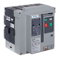
Eaton Magnum SB Series Instructions For Installation, Operation And Maintenance (70 pages)
Insulated Case Low Voltage Power
Brand:
Eaton
| Category:
Circuit breakers
| Size: 16.15 MB
Table of Contents
Table of Contents
2
Contents
5
Section 1: Introduction
5
General Information
5
Figure 1. Family of Magnum SB Low Voltage Power Fixed and Drawout Circuit Breakers (800-5000 Amperes)
6
Figures
6
Safety Features
6
Figure 2. Typical Magnum SB Nameplate
7
Safety Practices
7
Other Publications and Documentation
8
Qualified Personnel
8
Section 2: Receiving, Handling and Installation
8
General Information
8
Suggested Tools
8
Figure 3. Typical Magnum SB Designation Example
8
Unpacking Circuit Breaker
9
Storing Circuit Breaker
9
Figure 4. Shipping Clamps for Drawout Circuit Breaker
9
Lifting Circuit Breaker
10
Figure 5 . Magnum SB Circuit Breaker with Lifting
10
Yoke Attached
10
Circuit Breaker Inspection
11
Installing Drawout Circuit Breaker
11
Rejection Interlocks
11
Figure 7 . One Side of Drawout Circuit Breaker Properly
11
Figure 8. Cassette Rejection Interlock Pin Positioning/Installation for Standard and Double-Wide Frames
12
Figure 9 . Cassette Rejection Interlock Bracket Location
12
Figure 10. Remove Position
13
Figure 11. Disconnect Position
13
Figure 12. Test Position
13
Circuit Breaker Positioning
14
Levering Circuit Breaker
14
Figure 13. Connect Position
14
Figure 14. Cassette Label Showing Disconnected, Test and
14
Fixed Circuit Breaker
15
Circuit Breaker Operation
15
Figure 15. Levering Position Indication
15
Figure 16. Typical Fixed Magnum SB Circuit Breaker
15
Section 3: Circuit Breaker Description and Operation
16
Figure 17 . Typical Drawout Circuit Breaker Features
16
Introduction
16
Figure 18 . Typical SBS/SBSE Fixed Circuit Breaker Features
17
Figure 19 . Typical Double-Wide SBS/SBSE Standard Frame Fixed Circuit Breaker Features (Front and Rear Views)
18
Breaker Front Cover
19
Figure 20 . Typical Magnum SB Drawout Circuit
19
Basic Circuit Breaker Assembly
20
Figure 21. Typical Magnum Construction (Right Side View)
20
Figure 22 . Features of Magnum Moving
20
Pole Units
20
Primary Moving Contacts
20
Figure 23 . Narrow Frame (8-Finger) Moving
21
Figure 24. SBSE Moving Contact Assembly
21
Figure 25 . Standard Frame (12-Finger) Moving Conductor
21
Primary Stationary Contacts
21
Figure 27 . Typical Electrically Operated Drawout Circuit
22
Manual Operation
22
Operating Mechanism
22
Anti-Pump Feature
23
Arc Chambers
23
Arc Chute
23
Electrical Operation
23
Figure 28 . Circuit Breaker Closing Springs Being
23
Figure 29 . Electrical Motor Operator to Charge Closing
23
Electronic Tripping System
24
Figure 30 . Cross Section of Conductor and Arc
24
Figure 31. Magnum Arc Plate Assembly
24
Microprocessor-Based Trip Unit
24
Effective March
25
Current Sensors
26
Figure 34 . Digitrip RMS 1150 Programmable Trip Unit
26
Figure 35. Hand Held Tester
26
Rating Plug
26
Figure 36 . Replaceable Current Sensors Shown with
27
Fixed Instantaneous Non-Adjustable Setting
27
High Instantaneous Trip
27
Making Current Release
27
Mechanical Trip Flag
27
Trip Actuator
27
Figure 37. Line-Side Voltage Tap for 1150 Trip Unit
28
Figure 38. Top View Secondary Connectors
28
Figure 39. Secondary Connector Protective Hood
28
Secondary Contacts and Connection Diagrams
28
Voltage Taps
28
Connection Diagrams
29
Figure 40. Typical Cassette Mounted Secondary Wiring
29
Figure 41. AMP Secondary Wiring Removal Tool
29
Figure 42 . Connection Diagram for Narrow and Standard
30
Figure 43 . Connection Diagram for Narrow and Standard
31
Figure 44 . Connection Diagram for Narrow and Standard
32
Figure 45 . Connection Diagram for Standard SBSE Frame
33
Figure 46 . Connection Diagram for Standard SBSE Frame
34
Figure 47 . Connection Diagram for Standard SBSE Frame
35
Figure 48 . Connection Diagram for Double-Wide Frame (Except SBSE) with Digitrip 520 and 520M with ABCABC
36
Figure 49 . Connection Diagram for Double-Wide Frame
37
Figure 50. Connection Diagram for Double-Wide Frame (Except SBSE) with Digitrip 1150 with ABCABC Configuration
38
Figure 51 . Connection Diagram for Double-Wide Frame (Except SBSE) with Digitrip 520 and 520M with AABBCC
39
Figure 52 . Connection Diagram for Double-Wide Frame
40
Figure 53. Connection Diagram for Double-Wide Frame (Except SBSE) with Digitrip 1150 with AABBCC Configuration
41
Figure 54. Connection Diagram for SBSE Double-Wide Frame with Digitrip 520 and 520M with ABCABC Configuration
42
Figure 55. Connection Diagram for SBSE Double-Wide Frame with Digitrip 520MC with ABCABC Configuration
43
Figure 56 . Connection Diagram for SBSE Double-Wide Frame
44
Figure 57. Connection Diagram for SBSE Double-Wide Frame with Digitrip 520 and 520M with AABBCC Configuration
45
Figures
45
Figure 58. Connection Diagram for SBSE Double-Wide Frame with Digitrip 520MC with AABBCC Configuration
46
Figure 59 . Connection Diagram for SBSE Double-Wide Frame
47
Accessory Devices
48
Figure 60. Through-The-Window Electrical Accessories
48
Figure 61 . Shunt Trip with Cutoff Switch
48
Figure 62. Shunt Trip Switch Installed
48
Plug-In Electrical Accessories
48
Figure 63 . Spring Release with Optional Latch Check Switch . 49 Figure 64 . Undervoltage Release Device
49
Figure 65 . Shunt Trip, Spring Release and Undervoltage
49
Release Installed
49
Figure 66. Auxiliary Switch (2A/2B)
50
Figure 67 . Mechanical Trip Indicator with Associated
50
Internal Electrical Accessories
50
Figure 68. Motor Operator Kit
51
Figure 69 . Motor Operator Installed in Narrow Frame
51
Figure 70. Cover Mounted Key Lock and Operations Counter
51
Figure 71. Cassette Mounted Key Lock
52
Figure 72. ON-OFF Pushbutton Lockable Cover Plate
52
Mechanical Accessories
52
Figure 73. Typical Safety Shutters in Closed Position
53
Figure 74. Typical Safety Shutters in Open Position
53
Figure 75 . Cell Switch (Drawout Position Indicator)
53
Figure 76. Cell Switches Mounted on Cassette
53
Figure 77. Door Escutcheon and Gasket
53
Figure 78. IP54 Waterproof Cover
54
Figure 79 Cassette-Mounted 2-Way Cable Interlock
54
Section 4: Drawout Circuit Breaker and Cassette
55
General
55
Drawout Cassette
55
Figure 80. Drawout Circuit Breaker in Cassette
55
Figure 81 . Drawout Circuit Breaker with Automatic
55
Figure 82. Typical Drawout Cassette Features
56
Drawout Circuit Breaker Dimensions
57
Drawout Cassette Dimensions
57
Figure 83 . Typical Narrow Frame Cassette
57
Figure 84. Typical Basic Cassette (Without Stabs)
57
Figure 85. Typical Standard Cassette (Vertical Terminals)
57
Figure 86 . Typical Universal Cassette, 4-Pole
57
Section 5: Fixed Circuit Breaker
58
General
58
Fixed Circuit Breaker Dimensions
58
Section 6: Inspection and Maintenance
59
General
59
General Cleaning Recommendations
59
When to Inspect
59
Functional Field Testing
60
What to Inspect
60
Arc Chute Inspection
61
Electrical Operation Functional Test
61
Manual Operation Functional Test
61
Trip Unit Overload Functional Test
61
Figure 90. Bottom View of Arc Chute
62
Figure 91 . Primary Contacts with Circuit Breaker Open
62
Figure 92 . Contact Inspection Area with Circuit
62
Figures
62
Primary Contact Inspection
62
Breaker Frame Inspection
63
Figure 93 . Use of Contact Wear Indicator with Circuit
63
Breaker Mechanism Inspection
64
Figure 94. Magnum DS Lubrication
64
Figure 95. Magnum DS Lubrication
64
Figure 96. Magnum DS Lubrication
65
Figure 97 . Magnum DS Lubrication
65
Figure 98 . Magnum DS Lubrication
65
Figure 99. Magnum DS Lubrication
65
Circuit Breaker Modifications and Changes
66
Figure 100 . Magnum DS Lubrication-Levering-In
66
Figure 101 . Magnum DS Lubrication-Levering-In
66
Figure 102. Trip Unit Rating Plug Location
66
Rating Plug Replacement
66
Current Sensor Replacement
67
Figure 103. Current Sensor Cover in Place over Sensors
67
Figure 104. One Current Sensor Shown Removed and
67
Section 7: Troubleshooting
68
Introduction
68
Section 8: Renewal Parts
69
General
69
Advertisement
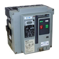
Eaton Magnum SB Series Technical Product Manual (153 pages)
Low Voltage Power Circuit Breaker
Brand:
Eaton
| Category:
Circuit breakers
| Size: 27.15 MB
Table of Contents
5 Magnum IEC - Product Specific Information
1
Table of Contents
2
1 Overview of the Magnum Low Voltage Circuit Breaker
4
Magnum DS Family
4
Magnum SB Family
6
Magnum IEC Family
7
Magnum DC Switch Family
8
2 Family Features and Characteristics
9
Universal Family Features
9
High Performance Interruption & Withstand Levels
9
Continuous Current Ratings
9
Sizes, Dimensions, Weights and Configurations
9
Design Configuration Flexibility
11
User Friendly
12
Front Cover Details Features
13
Construction Characteristics
14
Rigid Frame Housing
14
Three Piece Construction
14
Two-Step Stored Energy Mechanism
14
Unsurpassed Performance Design
14
Value Added Features
14
Breaker Mounting Configurations
14
Drawout Mounting
15
Cassettes - Available Styles
15
Renewal Parts for Extended Life and Longevity
16
3 Magnum DS - Product Specific Information
17
Standards and Certifications
17
Selection and Identification of Ratings for Magnum DS
17
Catalog Number Selection Table
18
Magnum DS - Continuous Amperage, Interruption and Withstand Ratings Tables
21
Magnum DS - Current Limiting Circuit Breakers
23
4 Magnum SB - Product Specific Information
25
Standards and Certifications
25
Selection and Identification of Ratings for Magnum SB
26
Catalog Number Selection Table
27
Magnum SB - Continuous Amperage, Interruption and Withstand Ratings Tables
30
Standards and Certifications
32
Selection and Identification of Ratings for Magnum IEC
33
Catalog Number Selection Table
34
Magnum IEC - Continuous Amperage, Interruption and Withstand Ratings Tables
37
6 Magnum DC - Product Specific Information
39
Standards and Certifications
39
Magnum DC Switches Selection
40
7 Magnum Trip Units and Communication Devices
41
Overview of Digitrip (TM) Electronic Trip Units
41
Digitrip Trip Units - Features
43
Digitrip Trip Units - Comprehensive Features
46
Additional Modules for Digitrip 1150 Trip Units
48
Other Communication Related Devices
50
Ground Fault Provisions and Protective Schemes
51
8 Accessory Devices and Connections
52
Overview of Magnum Accessories
52
Plug-In Electrical Accessories
52
Internal Electrical Accessories
54
Mechanical Accessories
55
9 Technical Data and Endurance Information for Installation
59
Technical Data for Usual Service Conditions (0°C to 40°C)
59
Quick Reference for Other Documents and Information - Outlined Drawings
62
10 Applications and Other Miscellaneous Engineering Data
63
Applications for Magnum Circuit Breakers
63
11 Magnum Drawings and Outlines
64
Table of Contents for Magnum Drawings and Outlines
64
Engineering Document References Chart
66
Advertisement
Related Products
Eaton Magnum DS Series
Eaton Magnum IEC Series
Eaton Magnum PXR
Eaton Magnum Power Defense SB
Eaton Magnum MR2
Eaton MPN-C08
Eaton MPN-416
Eaton MPN-C40
Eaton MPS-C20
Eaton MPS-616
Eaton Categories
UPS
Circuit breakers
Switch
Industrial Equipment
Industrial Electrical
More Eaton Manuals
Login
Sign In
OR
Sign in with Facebook
Sign in with Google
Upload manual
Upload from disk
Upload from URL