Sign In
Upload
Manuals
Brands
Eaton Manuals
Relays
EDR-5000
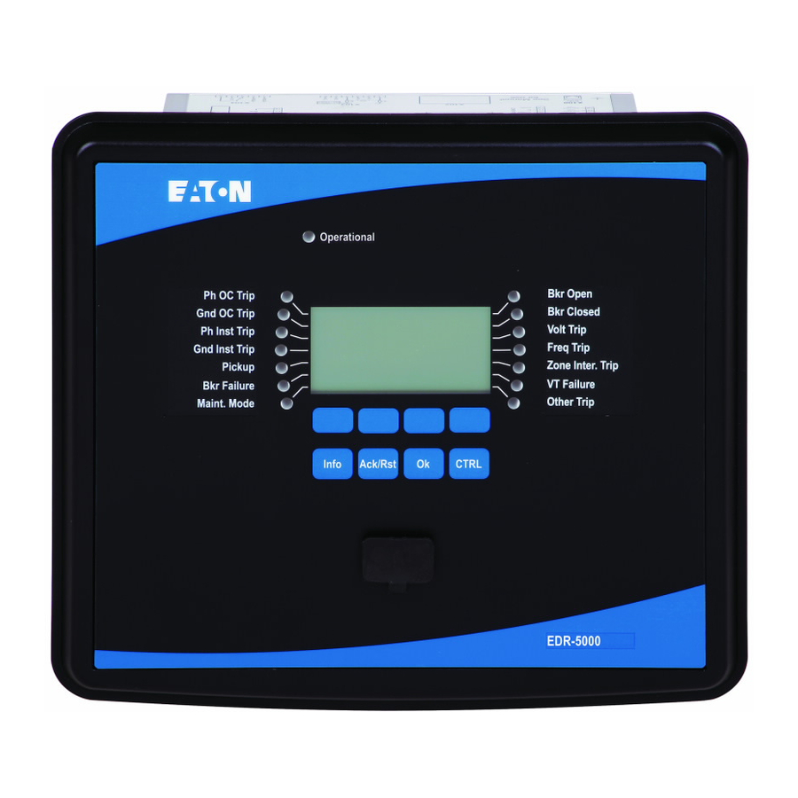
Eaton EDR-5000 Manuals
Manuals and User Guides for Eaton EDR-5000. We have
3
Eaton EDR-5000 manuals available for free PDF download: Nstallation, Operation And Maintenance Manual, Installation, Operation And Maintenance Manual, Cheat Sheet
Eaton EDR-5000 Nstallation, Operation And Maintenance Manual (1041 pages)
Distribution
Brand:
Eaton
| Category:
Relays
| Size: 12.06 MB
Table of Contents
EDR-5000 Functional Overview
2
Table of Contents
3
Comments on the Manual
9
What Is Included with the Device
13
Storage
13
Important Information
13
Symbols
14
General Conventions
16
Load Reference Arrow System
20
Device
21
Device Planning
21
Device Configuration Parameters of the Device
22
Installation and Wiring
26
Three-Side-View
26
Overview of Slots - Assembly Groups
28
Slot X1: Power Supply Card with Digital Inputs
30
Slot X2: Relay Output Card - Zone Interlock
33
Slot X3: Current Transformer Measuring Inputs
36
Slot X4: Voltage Transformer Measuring Inputs
46
Typical Connection Diagrams
53
Slot X2: Relay Output Card
57
Slot X6: Digital Inputs
60
Digital Inputs
60
Slot X100: Ethernet Interface
63
Slot X103: Data Communication
65
Slot X104: IRIG-B00X and Supervision Contact
69
Slot X120 - PC Interface
71
Control Wiring Diagram
72
Input, Output and LED Settings
73
Digital Input Configuration
73
DI-8P X
76
DI-8 X Settings
80
Wired Inputs (Aliases)
83
Relay Output Configuration
87
RO-4ZI X Settings
90
RO-6 X Settings
106
LED Configuration
128
The »System OK (Operational) « LED
131
LED Settings
132
Front Panel
149
Basic Menu Control
155
Powerport-E
156
Quality Manager
157
Measuring Values
158
Read out Measured Values
158
Current - Measured Values
160
Voltage - Measured Values
163
Power - Measured Values
167
Energy Counter
169
Global Parameters of the Energy Counter Module
169
Direct Commands of the Energy Counter Module
169
Signals of the Energy Counter Module (States of the Outputs)
170
Statistics
171
Configuration of the Minimum and Maximum Values
171
Configuration of the Average Value Calculation
172
Direct Commands
174
Global Protection Parameters of the Statistics Module
174
States of the Inputs of the Statistics Module
177
Signals of the Statistics Module
178
Counters of the Module Statistics
178
System Alarms
187
Demand Management
187
Peak Demand
190
Min. and Max. Values
190
THD Protection
190
Device Planning Parameters of the Demand Management
191
Signals of the Demand Management (States of the Outputs)
191
Global Protection Parameter of the Demand Management
192
States of the Inputs of the Demand Management
195
Resets
196
Manual Acknowledgment
198
External Acknowledgments
199
Manual Resets
200
Reset to Factory Defaults
200
Status Display
201
Operating Panel (HMI)
202
Special Parameters of the Panel
202
Direct Commands of the Panel
202
Global Protection Parameters of the Panel
202
Recorders
203
Waveform Recorder
203
Fault Recorder
212
Event Recorder
219
Trend Recorder
220
Time Synchronization
225
Accuracy of Time Synchronization
226
Sntp
233
Irig-B00X
241
Device Parameters
246
Date and Time
246
Version
246
TCP/IP Settings
247
Direct Commands of the System Module
248
Global Protection Parameters of the System
249
System Module Input States
251
Special Values of the System Module
253
Communication Protocols
254
Module: SCADA
254
TCP/IP Parameter
255
Modbus
256
Profibus
278
Iec 61850
292
Dnp3
308
Parameters
351
Parameter Definitions
351
Access Authorizations (Access Areas)
372
Passwords - Areas
372
How to Find out What Access Areas/Levels Are Unlocked
375
Unlocking Access Areas
376
Changing Passwords
376
Password Entry at the Panel
377
Password Forgotten
377
Parameter Setting at the HMI
378
Setting Groups
383
Program Mode
394
System Parameters
395
General System Parameters
395
System Parameters - Current Related
396
System Parameters - Voltage Related
397
Blocking
399
Permanent Blocking
399
Temporary Blocking
400
To Activate or Deactivate the Tripping Command of a Protection Module
401
Activate, Deactivate Respectively to Block Temporary Protection Functions
402
Protection (Prot) Module
404
How to Block All Protective and Supervisory Functions
404
Direct Commands of the Protection Module
411
Global Protection Parameters of the Protection Module
411
Protection Module Input States
412
Protection Module Signals (Output States)
412
Values of the Protection Module
413
Switchgear/Breaker - Manager
414
Single Line Diagram
415
Switchgear Configuration
415
Switchgear Wear
435
Control Parameters
443
Control - Example: Switching of a Breaker
455
Protective Elements
458
Directional Feature - Phase Current
458
50P/67P - DEFT Overcurrent Protection
461
Overcurrent Protection [51, 51C, 51V, 67]
471
Directional Features for Measured (IX) Ground Fault Elements 50X/51X
488
50X/67X DEFT Measured Ground Fault Protection
491
51X/67X INV Measured Ground Fault Protection
500
Directional Features for Calculated (IR) Ground Fault Elements 50R/51R
509
50R/67R DEFT Calculated Ground Fault Protection
512
51R/67R INV Calculated Ground Fault Protection
520
ZI - Zone Interlocking
529
46 - Current Unbalance Protection
544
CLPU - Supervision Module Cold Load Pickup
552
SOTF - Switch Onto Fault Protection
561
79 - Automatic Reclosure
568
27M - Undervoltage Protection
606
59M - Overvoltage Protection
615
27A - Auxiliary Undervoltage Protection
623
59A - Auxiliary Overvoltage Protection
629
59N - Neutral Overvoltage
634
25 - Sync-Check
640
47 - Voltage Unbalance Protection
664
81O/U, 81R, 78V - Frequency Protection
672
32 - Power Protection
697
32V - Reactive Power Protection
710
55A and 55D - PF Protection
723
Q->&V< Reactive-Power/Undervoltage Protection
734
Reconnection Module
746
27(T) - LVRT - Low Voltage Ride through
771
UFLS under Frequency Load Shedding
785
Exp - External Protection
803
Supervision
809
BF- Breaker Failure [50BF*/62BF]
809
CTS - Current Transformer Supervision
834
LOP - Loss of Potential
841
74TC - Trip Circuit Monitoring
847
Device Planning Parameters of the Trip Circuit Monitoring Module
850
Self Supervision
854
Programmable Logic
859
General Description
859
Programmable Logic at the Panel
865
Commissioning
869
Commissioning/Protection Test
870
Decommissioning - Removing the Plug from the Relay
871
Service and Commissioning Support
872
Maintenance Mode
873
Principle - General Use
873
Before Use
874
How to Use the Maintenance Mode
874
Forcing the Relay Output Contacts
876
Disarming the Relay Output Contacts
877
Forcing Rtds
879
Forcing Analog Outputs
880
Forcing Analog Inputs
881
Failure Simulator (Sequencer)
882
Degree of Protection en 60529
901
Routine Test
901
Housing
901
Technical Data
901
Climatic Environmental Conditions
901
Current and Ground Current Measurement
902
Voltage and Residual Voltage Measurement
904
Frequency Measurement
904
Voltage Supply
905
Power Consumption
905
Display
906
Front Interface USB
906
Real Time Clock
906
Digital Inputs
907
Relay Outputs
908
Supervision Contact (SC)
908
Time Synchronization IRIG-B00X
908
Zone Interlocking
909
Rs485
909
LWL-Module with ST Connector
909
Optical Ethernet Module with LC Connector
910
URTD-Interface
910
Boot Phase
910
Standards
911
Approvals
911
Design Standards
911
High Voltage Tests (IEC 60255-1)
911
EMC Immunity Tests
912
EMC Emission Tests
913
Environmental Tests
914
Mechanical Tests
916
Specifications
917
Specifications of the Real Time Clock
917
Time Synchronization Tolerances
917
Specifications of the Measured Value Acquisition
918
Protection Elements Accuracy
920
Appendix
928
Instantaneous Current Curves (Phase)
938
Time Current Curves (Phase)
939
Instantaneous Current Curves (Ground Current Calculated)
951
Instantaneous Current Curves (Ground Current Measured)
953
Time Current Curves (Ground Current)
955
Assignment List
967
List of ANSI Codes
1039
Advertisement
Eaton EDR-5000 Installation, Operation And Maintenance Manual (1017 pages)
Brand:
Eaton
| Category:
Relays
| Size: 14.12 MB
Table of Contents
EDR-5000 Functional Overview
2
Table of Contents
3
Comments on the Manual
9
What Is Included with the Device
14
Storage
14
Important Information
14
Symbols
15
General Conventions
21
Load Reference Arrow System
22
Device
23
Device Planning
23
Device Planning Parameters of the Device
24
Installation and Wiring
26
Three-Side-View
26
Overview of Slots - Assembly Groups
28
Slot X1: Power Supply Card with Digital Inputs
30
Slot X2: Relay Output Card - Zone Interlock
33
Slot X3: Current Transformer Measuring Inputs
36
Slot X4: Voltage Transformer Measuring Inputs
46
Typical Connection Diagrams
52
Slot X2: Relay Output Card
56
Slot X6: Digital Inputs
59
Digital Inputs
59
Slot X100: Ethernet Interface
62
Slot X103: Data Communication
64
Slot X104: IRIG-B00X and Supervision Contact
69
Slot X120 - PC Interface
71
Control Wiring Diagram
72
Input, Output and LED Settings
74
Digital Input Configuration
74
DI-8P X
75
DI-8 X Settings
79
Wired Inputs (Aliases)
83
Relay Output Configuration
87
RO-4ZI X - Settings
90
RO-6 X Settings
107
LED Configuration
130
The »System OK (Operational) « LED
133
LED Settings
134
Front Panel
151
Basic Menu Control
157
Powerport-E Keyboard Commands
158
Powerport-E
159
Installation of Powerport-E
160
Uninstalling Powerport-E
160
Setting up the Connection PC - Device
161
Restoring Device Data When Using Powerport-E
172
Loading of Device Data When Using Powerport-E
172
Backup and Documentation When Using Powerport-E
173
Printing of Device Data When Using Powerport-E (Setting List)
173
Off-Line Device Planning Via Powerport-E
175
Powerport-E Keyboard Commands
176
Measuring Values
177
Read out Measured Values
177
Current - Measured Values
180
Voltage - Measured Values
183
Power - Measured Values
187
Energy Counter
189
Global Parameters of the Energy Counter Module
189
Direct Commands of the Energy Counter Module
189
Signals of the Energy Counter Module (States of the Outputs)
189
Statistics
191
Configuration of the Minimum and Maximum Values
191
Configuration of the Average Value Calculation
192
Direct Commands
194
Global Protection Parameters of the Statistics Module
194
States of the Inputs of the Statistics Module
197
Signals of the Statistics Module
198
Counters of the Module Statistics
198
System Alarms
207
Demand Management
207
Peak Demand
210
Min. and Max. Values
210
THD Protection
210
Device Planning Parameters of the Demand Management
211
Signals of the Demand Management (States of the Outputs)
211
Global Protection Parameter of the Demand Management
212
States of the Inputs of the Demand Management
216
Resets
217
Manual Acknowledgment
219
Manual Acknowledgment Via Powerport-E
219
External Acknowledgments
220
External Acknowledge Via Powerport-E
220
External LED - Acknowledgment Signals
221
Manual Resets
231
Manual Resets Via Powerport-E
231
Reset to Factory Defaults
231
Status Display
232
Status Display Via Powerport E
232
Operating Panel (HMI)
233
Special Parameters of the Panel
233
Direct Commands of the Panel
233
Global Protection Parameters of the Panel
233
Recorders
234
Waveform Recorder
234
Fault Recorder
245
Event Recorder
254
Trend Recorder
258
Time Synchronization
264
Accuracy of Time Synchronization
265
Sntp
272
Irig-B00X
280
Device Parameters
285
Date and Time
285
Version
285
Version Via Powerport-E
285
TCP/IP Settings
286
Direct Commands of the System Module
287
Global Protection Parameters of the System
288
System Module Input States
290
System Module Signals
291
Special Values of the System Module
292
Communication Protocols
293
Modbus
293
Iec 61850
300
Parameters
315
Parameter Definitions
315
Access Authorizations (Access Areas)
330
Passwords - Areas
330
How to Find out What Access Areas/Levels Are Unlocked
334
Unlocking Access Areas
334
Changing Passwords
335
Adaptive Parameters Via HMI
336
Access Authorizations (Access Areas)
339
Passwords - Areas
339
How to Find out What Access Areas/Levels Are Unlocked
343
Unlocking Access Areas
344
Changing Passwords
344
Changing Passwords Via Power-Port-E
345
Password Entry at the Panel
345
Password Forgotten
345
Parameter Setting at the HMI
346
Parameter Setting Via Power-Port-E
350
Setting Groups
353
Comparing Parameter Files Via Powerport-E
366
Converting Parameter Files Via Powerport-E
367
Program Mode
368
System Parameters
369
General System Parameters
369
System Parameters - Current Related
370
System Parameters - Voltage Related
371
Blocking
373
Permanent Blocking
373
Temporary Blocking
373
To Activate or Deactivate the Tripping Command of a Protection Module
375
Activate, Deactivate Respectively to Block Temporary Protection Functions
376
Protection (Prot) Module
378
How to Block All Protective and Supervisory Functions
378
Direct Commands of the Protection Module
385
Global Protection Parameters of the Protection Module
385
Protection Module Input States
386
Protection Module Signals (Output States)
386
Values of the Protection Module
387
Switchgear/Breaker - Manager
388
Breaker Configuration
388
Single Line Diagram
390
Switching the Breaker at the Panel
412
Breaker Wear
414
Control - Example: Switching of a Breaker
431
Protective Elements
434
Directional Feature - Phase Current
434
50P/67P - DEFT Overcurrent Protection
437
Overcurrent Protection [51, 51C, 51V, 67]
447
Directional Features for Measured (IX) Ground Fault Elements 50X/51X
465
50X/67X DEFT Measured Ground Fault Protection
468
51X/67X INV Measured Ground Fault Protection
478
Directional Features for Calculated (IR) Ground Fault Elements 50R/51R
488
50R/67R DEFT Calculated Ground Fault Protection
491
51R/67R INV Calculated Ground Fault Protection
501
ZI - Zone Interlocking
511
46 - Current Unbalance Protection
529
CLPU - Supervision Module Cold Load Pickup
537
SOTF - Switch Onto Fault Protection
546
79 - Automatic Reclosure
554
27M - Undervoltage Protection
591
59M - Overvoltage Protection
600
27A - Auxiliary Undervoltage Protection
608
59A - Auxiliary Overvoltage Protection
615
59N - Neutral Overvoltage
622
25 - Sync-Check
629
47 - Voltage Unbalance Protection
653
81O/U, 81R, 78V - Frequency Protection
661
32 - Power Protection
686
32V - Reactive Power Protection
699
55A and 55D - PF Protection
712
Q->&V< Reactive-Power/Undervoltage Protection
722
LVRT - Low Voltage Ride through
744
Exp - External Protection
759
Supervision
765
BF- Breaker Failure [50BF*/62BF]
765
CTS - Current Transformer Supervision
791
LOP - Loss of Potential
798
74TC - Trip Circuit Monitoring
804
Self Supervision
812
Programmable Logic
815
General Description
815
Programmable Logic at the Panel
821
Programmable Logic Via Powerport-E
821
Commissioning
848
Commissioning/Protection Test
849
Decommissioning - Removing the Plug from the Relay
850
Service and Commissioning Support
851
Maintenance Mode
852
Principle - General Use
852
Before Use
853
How to Use the Maintenance Mode
853
Forcing the Relay Output Contacts
855
Disarming the Relay Output Contacts
856
Forcing Rtds
858
Forcing Analog Outputs
859
Forcing Analog Inputs
860
Failure Simulator (Sequencer)
861
Technical Data
880
Climatic Environmental Conditions
880
Degree of Protection en 60529
880
Routine Test
880
Housing
881
Current and Ground Current Measurement
882
Voltage and Residual Voltage Measurement
884
Frequency Measurement
884
Voltage Supply
885
Power Consumption
885
Display
886
Front Interface RS232
886
Real Time Clock
887
Digital Inputs
888
Relay Outputs
889
Supervision Contact (SC)
889
Time Synchronization IRIG-B00X
890
Zone Interlocking
891
Rs485
892
Fiber Optic
892
URTD-Interface
892
Boot Phase
893
Standards
894
Approvals
894
Design Standards
894
High Voltage Tests (IEC 60255-1)
894
EMC Immunity Tests
895
EMC Emission Tests
896
Environmental Tests
897
Environmental Tests
898
Mechanical Tests
899
Specifications
900
Specifications of the Real Time Clock
900
Time Synchronization Tolerances
900
Specifications of the Measured Value Acquisition
901
Protection Elements Accuracy
903
Appendix
910
Instantaneous Current Curves (Phase)
920
Time Current Curves (PHASE)
921
Instantaneous Current Curves (Ground Current Calculated)
933
Instantaneous Current Curves (Ground Current Measured)
935
Time Current Curves (Ground Current)
937
Assignment List
949
List of ANSI Codes
1015
Eaton EDR-5000 Cheat Sheet (4 pages)
Brand:
Eaton
| Category:
Relays
| Size: 0.53 MB
Table of Contents
Main Screen
1
How to Review Cause of Trip and Fault Condition of the Leds
1
How to Reset Latched Leds and Relay Outputs
2
How to View Measured Values
3
How to Navigate the Faceplate Menu
4
Advertisement
Advertisement
Related Products
Eaton EDR 3000
Eaton EASY-E4-UC-12RC1
Eaton EASY-E4-UC-16RE1
Eaton easySafety ES4P-221-DMXD1
Eaton ESR5-VE3-42
Eaton EASY512-AB-RCX
Eaton easySafety ES4A-MEM-CARD1
Eaton EMR5-W380-1
Eaton EMR5-W500-1-D
Eaton easy800-SWD
Eaton Categories
UPS
Circuit breakers
Switch
Industrial Equipment
Industrial Electrical
More Eaton Manuals
Login
Sign In
OR
Sign in with Facebook
Sign in with Google
Upload manual
Upload from disk
Upload from URL