Sign In
Upload
Manuals
Brands
Eaton Manuals
Relays
EASY-E4-DC-12TCX1
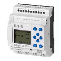
Eaton EASY-E4-DC-12TCX1 Manuals
Manuals and User Guides for Eaton EASY-E4-DC-12TCX1. We have
2
Eaton EASY-E4-DC-12TCX1 manuals available for free PDF download: Manual, Instruction Leaflet
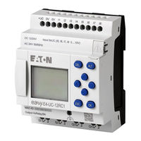
Eaton EASY-E4-DC-12TCX1 Manual (622 pages)
Brand:
Eaton
| Category:
Relays
| Size: 5.53 MB
Table of Contents
Imprint
2
Before Starting with the Installation
3
Table of Contents
5
Figure 13: Connecting the Power Supply
6
Figure 14: Connect Digital Inputs
6
Figure 15: Connect Digital Counter Inputs
6
Figure 16: Connecting Analog Inputs
6
Figure 17: Connecting Relay Outputs
6
About this Manual
17
List of Revisions
17
Target Group
17
Legal Disclaimer
18
Short Designations
19
Warning Labels
20
Writing Conventions
20
Documents with Additional Information
21
1 Easye4 Control Relays Description
23
Function
23
Use as Intended
23
Features
24
Device Models - Versions and Part Nos
25
Basic Features
25
Base Device Versions
26
Appendix
26
Figure 1: Devices with Display and Button Controls
26
Figure 2: Devices with LED Indicators Used for Diagnostics
26
Figure 3: Device Models in 4SU
27
Figure 4: Device Models in 2SU
27
I/O Expansion Versions EASY-E4
27
Accessory Devices
28
Nameplate
29
What the Different Parts of the Part Number Mean
29
Support
30
Overview of Devices
31
Programming Software Easysoft
32
Basics
33
Mandatory Requirements, Personnel Requirements
33
Occupational Safety
33
Personnel Qualifications
33
Safety Regulations
33
Device Documentation
34
Installation, Maintenance, and Disposal
34
Prerequisites for Proper Operation
35
Device-Specific Hazards
36
Electrostatic Discharge
36
Interferences
36
Data Loss
37
Safely Diverting Electrical Interference Currents
37
Short-Circuit Hazard
37
Stray Currents
37
Installation Cut-Out
38
Mechanical Forces on the Ethernet Port
38
Pointy, Sharp Objects and Corrosive Liquids
38
UV Light
38
2 Installation
41
Installation Position
42
Prerequisites for the Location of Use
42
Temperatures
42
Aeration and De-Aeration
43
Ambient Climatic Conditions
43
Unpacking and Checking the Equipment Supplied
44
Control Relays Mounting
45
Mounting Easye4 Control Relays
45
Figure 5: Mounting Distance Min. 3 CM
46
Figure 6: Assembling a Base Device with Expansions
47
Figure 7: Installation on IEC/EN 60715 Mounting Rail
48
Finishing up the Process
49
Mounting Additional Expansions
49
Mounting the First Expansion
49
Figure 8: Inserting a Fastening Bracket
50
Figure 9: Screw Mounting Configuration for a Device
50
Screw Mounting
50
Figure 10: Remove Adjacent Connectors
51
Figure 11: Dismantling
51
Removing a Device
51
Cable Cross-Sections
52
Connection Terminals
52
Figure 12: Screw Length Stripping Length
52
Cable Protection
53
Connecting the Power Supply
53
System Test
53
Connect Digital Inputs
54
Connect Digital Counter Inputs
55
Connecting Analog Inputs
56
Tips for Analog Signals
57
Connecting Relay Outputs
58
Connecting Transistor Outputs
59
Figure 18: Connecting Base Device Transistor Outputs
59
Figure 19: Connecting Expansion Device Transistor Outputs
59
Figure 20: Inductive Load with Suppressor Circuit
60
Connecting Outputs in Parallel
61
Transistor Output Behavior in the Event of a Short Circuit/Overload57
61
Analog I/O Expansion Device
62
Figure 21: Device Parameters Tab
62
Figure 22: Connecting Analog Inputs EASY-E4-DC-6AE1
62
Terminal Configurations for Individual Devices
64
External Connection Layouts
65
Inserting a Microsd Card
66
Memory Card
66
Remove Microsd
67
Ethernet
68
Connecting the Ethernet Cable
69
Removing the Ethernet Cable
69
Programming Software License
70
Licensing
71
System Requirements
71
Getting a License Key
72
Adding a License Key Later on
73
Software Updates and Hardware Changes
74
Installation Instructions
75
Daily Operation
79
Initial Commissioning
79
Startup Behavior of the Control Relays with LED Indicators
80
Switch on
80
LED Ethernet/Net
81
LED POW/RUN Expansion Unit
81
Startup Behavior of the Control Relays with a Display and Keypad
82
Changing the Menu Language
83
Startup Behavior of Base Devices with Connected Expansion Devices
84
Status Display on the Control Relays with Display and Keypad
85
Commissioning the Ethernet Network
87
Network Operation
87
Remote Operation
88
Overview of Switch-On Behavior
89
Startup Procedure with Device Initialization
90
Base Device with Display and Buttons
91
LCD Display
91
Keyboard
92
4 Operation
91
Display Color Backlight
92
Selecting Menus and Entering Values
93
Cursor Display
94
Entering of Values
94
RUN Mode
95
STOP Mode
95
Operating Modes of the Easye4
95
Operating Principle in the Circuit Diagram and Function Block Editor
97
Operation of the Menu Selection and Value Entry
97
How to Navigate the Device Menus
97
Selecting a Device Menu
98
Main Menu
99
Overview of the Menus on the Device
99
STOP RUN Operating Mode Menu
99
Menu Parameter
100
Set Clock Menu
101
Menu Card
102
Menu Information
103
System Options Menu
104
Program Menu
106
Your First EDP Program
108
Circuit Diagram Display
109
Draw a Wiring Diagram
110
From the First Contact to the Output Coil
111
Wiring
112
Saving
113
Testing the Circuit Diagram
114
Control Options in RUN Mode
115
Status Display During RUN Mode
115
Test Using the Power Flow Display
115
Power Flow Display with Zoom Function
116
Delete Program
117
Application Examples
118
Transfer Program to the Easye4 Device
118
Transfer with a Microsd Memory Card
118
Establish Ethernet Connection
123
5 Programming on the Device
125
Circuit Diagram Display
126
Circuit Diagram Elements
128
Function Blocks
128
Relays
128
Contacts
129
Coils
130
"Set" and "Reset" Coil Functions
132
Coil Negation (Inverse Contactor Function)
133
Evaluating a Rising Edge (Cycle Pulse)
133
Evaluating a Falling Edge (Cycle Pulse)
134
Markers and Analog Operands
135
Numeric Formats
136
Retentive Markers
136
Working with Contacts and Coils
137
Entering and Modifying Contacts
138
Changing an N/O Contact to an N/C Contact
139
Entering and Modifying Coils
140
Deleting Contacts and Coils
141
Creating and Modifying Connections
142
Deleting Connections
143
Adding a Rung
143
Deleting a Rung
143
Saving the Circuit Diagram
144
Got to a Rung
144
Exiting the Circuit Diagram Without Saving
145
Searching for Contacts and Coils
145
Switching with the Cursor Buttons
146
Checking the Circuit Diagram
147
Jumps
148
Example for Jumps
149
Power Flow Display of Skipped Area
149
Wiring NET Operands in the Circuit Diagram
150
Several NET Stations with Their Own Circuit Diagram
151
SN-RN Combination for Bit Exchange on the NET
152
SN-RN Example
152
NET Marker
153
NET Operand GT.. (Receive), PT.. (Send) and SC.. (Set Date and Time)
153
Transferring Programs from and to a Memory Card
154
Configuration on Base Devices with a Display
155
PROGRAMS Submenu
156
Start Program
156
Card - Device
157
Device - Card
157
Working with Function Blocks
158
Adding Function Blocks to the Circuit Diagram for the First Time
158
Function Block List
160
Configuring Parameters in the Function Block Editor
161
Assigning Operands at a Manufacturer Function Block's Input
162
Assigning Operands at a Manufacturer Function Block's Output
163
Deleting Operands at Function Block Inputs/Outputs
163
Behavior of the Function Block Editor with Different Operating Modes
163
PARAMETERS Menu
164
Deleting Function Blocks
164
Deleting Function Blocks from the Function Block List
165
Tips for Working with Manufacturer Function Blocks
165
Organizing Marker Ranges
167
6 Function Blocks
170
HW - Weekly Timer (Hour Week)
172
Manufacturer Function Blocks
172
Timer Modules
172
Assigning Operands
173
Parameter Definition at the Function Block
174
Parameter Set
174
Behavior in the Event of a Power Failure
175
HY - Year Time Switch (Hora Year)
182
Operating Principle
183
Switching Behavior with Overlapping Channel Settings
183
Function Block Outputs
184
The Function Block and Its Parameters
184
Parameterization
185
Setting Time Range Parameters
186
Setting Overlapping Time Ranges
187
Example 1: Select Year Range
188
Example 2: Select Month Ranges
188
Example 3: Select Day Ranges
188
Example 4: Select “Public Holidays"
189
Example 5: Select Time Range
190
Example 6: Specific Days of Specific Months
190
Example 7: Overlapping Ranges
191
OT - Operating Hours Counter
192
Function Block Inputs
193
RC - Real-Time Clock
196
T - Timing Relay
199
Interpretation of Variable Operands
201
Variable Time Values
201
Signal Diagrams
203
Signal Diagram of Timing Relay, On-Delayed
204
How the Timing Relay Works with the Off-Delayed Operating Mode
205
Signal Diagram of Timing Relay, Off-Delayed
206
Operational Diagrams Timing Relay, on and off Delayed 1
208
Signal Diagram Timing Relay, Single Pulse 1
209
Signal Diagram Timing Relay, Single Pulse 2
210
Retention
211
YT - Year Time Switch (Year Table)
213
Example 5: Specific Days of Specific Months
218
WT - Weekly Timer (Weektable)
219
Counter Function Blocks
222
C - Counter Relay
222
Signal Diagram of Counter Relay
226
CF - Frequency Counter
228
Signal Diagram of Frequency Counter
232
CH - High-Speed Counter
234
Signal Diagram High-Speed Counter
238
CI - Incremental Counter
241
Negative Count Direction
242
Signal Diagram High-Speed Incremental Value Counter
246
Arithmetic and Analog Function Blocks
248
A - Analog Value Comparator
248
Analog Comparator Signal Diagram
252
Example of an Analog Comparator When Using EDP Programming Language
253
Example of an AR Configuration on a Device Display
253
AR - Arithmetic
254
CP – Comparator
259
LS - Value Scaling
263
MM - Min-/Max Function
268
PW - Pulse Width Modulation
271
Manipulated Variable SV
272
Parameter Limits for Period Duration and Minimum on Duration
273
Minimum Period Duration PD
273
Minimum Contact Closing Time ME
273
Minimum on Duration = Minimum off Duration
273
Open-Loop and Closed-Loop Function Blocks
276
DC - PID Controller
276
Integral Component
277
Differential Component
277
Manual Mode of the PID Controller
278
KP Proportional Gain Factor
278
Scan Time Tc
279
Example of a PID Controller with the Programming Method EDP
281
Example of a PID Controller Configuration on a Device Display
281
FT - PT1-Signal Smoothing Filter
283
Cycle Time to Scan Time
284
PO - Pulse Output
288
Signal Diagram for Jog Mode
290
Positioning with a Specified Number of Steps P1 (Defined Distance)
290
Positioning at a Specified Jog Frequency PF
290
Normal Mode
291
Signal Diagram Normal Operation
296
Start Frequency FS
297
Operating Frequency FO
298
Jog Frequency PF
298
Frequency Change Per Step in the Acceleration Phase RF
298
Frequency Change Per Step in the Braking Phase RF
298
Connecting a Pulse Output Function Block
299
Parameters for Normal Operation
299
Parameters for Jog Operation
299
Evaluation of a Pulse Output Contact
300
Resetting a Pulse Output Function Block
300
TC - Three Step Controller
301
Level Control
305
VC - Value Limitation
306
Data and Register Function Blocks
310
BC - Block Compare
310
BT - Block Transfer
315
Transfer with Offset
315
Parameter Error Due to Incorrect Number or Offset Definition
316
Copy Mode, Operating Mode = CPY
317
Initialization Mode, Operating Mode = INI
317
DB - Data Function Block
321
Example of a Data Function Block with Programming Method EDP
324
Example of a DB Configuration on a Device Display
324
MX - Data Multiplexer
326
SR - Shift Register
330
SR Function Block - Shift Register (BIT)
330
SR Function Block - Shift Register (DWORD)
331
Example: Shift Register DW Mode, Backward
332
SR01 Configuration on Device Display
336
TB - Table Function
338
Writing to a Table
338
Reading from the Table
338
Example of a Table Function When Using the EDP Programming Language
341
NET Function Blocks
343
GT - Get Values from NET
343
PT - Put Values to NET
346
SC - Synchronizing Clock Via NET
350
AL - Alarm Function Block
353
BV - Boolean Operation
357
D - Text Display
361
Text Display Tab
363
Display Priority
364
Rolling Time
364
Alarm
364
Activation P Buttons
364
Default Colors Tab
365
Languages Tab
365
Type and Operand
366
Signal Diagram for Text Displays with Different Priorities
367
Signal Diagram for Text Displays with Identical Priorities
367
Entering Data on the Display Via a D Text Function Block
368
D - Text Display Editor
370
Properties Text Display Editortext Display Editor
370
Working with the Text Display Editor
370
Color Management in the Display Text Editor
371
Insert Special Characters
372
Display and Input Elements
372
Value Display
372
Bar Graph
373
Static Text
374
Running Text
374
Rolling Text
375
Unconditional Display
375
Associated Variable
375
Message Text
376
Date and Time Display
377
Timing Relay Value Display
378
Value Entry
379
Latching Button
381
Message Text Selection
382
Date and Time Entry
382
Timing Relay Value Entry
382
DL - Data Logger
384
Storage Mode
387
Number of Files Per Log Session
387
Number of Data Sets Per Log File
388
Log When Input Values Change
388
Reading Log Files
388
Sample Log File
388
JC - Conditional Jump
390
Active Function Blocks
390
Skipped Function Blocks
391
Positioning in the Function Block Diagram
391
LB - Jump Label
395
Linking and Parameter Setting
395
MR - Master Reset
397
NC - Numerical Converter
401
BCD Mode
402
BIN Mode
402
Example for bin Operating Mode
403
Example for BCD Operating Mode
405
ST - SET Cycle Time
407
Interrupt Function Blocks
409
IC - Counter-Controlled Interrupt Function Block
409
Execution Time for an Interrupt
409
Interaction between Main Program and Interrupt Program
410
Available Functions Within an Interrupt Program
411
Monitoring the Interrupt Load
414
Measuring the Interrupt Load
416
Available Fixes for High Interrupt Loads
416
IE - Edge-Controlled Interrupt Function Block
422
IT - Time-Controlled Interrupt Function Block
428
UF - User Function Block
436
Creating a User Function Block
437
Name and Version
439
Configuring a User Function Block
439
Interface Section
441
Know-How Protection Section
441
Retention Section
441
Read from Program
441
Retention Bytes
442
Retain Retention During Transfer
442
Programming a User Function Block
443
Calling a User Function Block in the Main Program
444
User Function Block in and FBD Main Program
444
Inputs/Outputs Wiring
445
Analog Contact Tab
447
Coil Tab
447
User Function Blocks in an ST Main Program
448
Saving a User Function Block
449
Operands Available for User Function Blocks
449
Programming View Tabs
451
Exporting a User Function Block
451
Supported Manufacturer Function Blocks
451
Plausibility Check
452
Importing a User Function Block
453
Replacing a User Function Block
454
Deleting a User Function Block
455
Comparing User Function Blocks
455
Printing a User Function Block
457
Timing and Counter Relay Example
458
Entering Function Block Parameters
459
System Settings
463
System Options - Base Device with Display and Buttons
464
View
465
Device ID
465
Boot Logo
466
Image as on the Display
466
Net
467
Bus Delay
467
System Settings - Ethernet
468
Remote RUN
468
Switch Languages
469
Selecting a Menu Language on a Base Device with a Display
469
Setting the Menu Language in the Easysoft 7
469
Setting the Startup Behavior
470
Enabling / Disabling the RUN START Option
470
Configuration on a Base Device with a Display
470
Enabling / Disabling the CARD START Option
471
Configuring the Easysoft 7
471
Debounce
473
Configuring Input Debouncing on a Base Device with a Display
473
Configuring Input Debouncing in Easysoft 7
473
Download Comments
474
P Buttons
475
Configuring the P Buttons on a Base Device with a Display
475
Configuring the P Buttons in Easysoft 7
475
Define Program Name
476
Retention Function
477
Retention in the Easysoft 7
478
Security – Password Protection
480
Configuring the Password on a Base Device with a Display
480
Defining Password-Protected Areas
480
Assigning a Password
481
What Happens if You Forget Your Password or Enter the Wrong Password
482
Enabling the Password
482
Changing a Password
482
Removing Password Protection
482
Configuring the Password in Easysoft 7
483
Configuring the Memory Card and Device ID
485
Time and Date Setting
486
DST Setting DST
486
Setting Radio Clock
487
Setting Time and Date in the Easysoft 7
488
Net-Group
488
Microsd Memory Card
491
Automatic Booting from the Card
492
Preparing the Card in the PC for Booting with Easysoft 7
492
Transfer Program
493
Setting a Program as the Starting Program
494
Preparing the Card in the Unit for Booting with Easysoft 7
495
Preparing the Card for Booting on the Unit Itself
499
Reset – Resetting the Device to Factory Settings
501
Loading New Operating System
502
Setting a Splash Screen
504
The Unit Inside
505
Program Execution
505
How the EDP Evaluates Circuit Diagrams and Function Blocks
507
Transfering an Existing Circuit Diagram
508
Timing Characteristics of Expansion Devices
509
Time Behavior of the Inputs and Outputs
510
Input Delay (Debounce)
510
Delay Time on EASY-E4-DC-... Devices
511
Delay Time with DEBOUNCE Activated
511
Delay Time with DEBOUNCE Deactivated
512
Delay Time on EASY-E4-UC-... Devices
513
Additional Delay Time Due to Bouncing Pushbuttons
514
Device Information
515
Operating States
516
Switched Off- no Supply Voltage Available
516
Powered up
516
NET Network
517
Life Signs NET Stations
518
Diagnostics Messages of the Operating System
521
Transistor Outputs (Overload / Short Circuit)
522
Diagnostics Buffer
522
Connection to Other Devices
525
Functions Offline
526
Establish a Connection to the Device
526
Configuring Ethernet and NET Settings Without a Program
528
Configuring Ethernet and NET Settings Based on an Opened Project
529
Program/Configuration
529
Clock
532
Display
532
Circuit Diagram Window in Communication View
532
Online Status Display
533
Status Display on
534
Wiring Test
535
Group Diagnostic Alarms
535
Establishing an Ethernet Connection
536
Setting up a NET
541
NET - a Group
541
Between Groups
541
Access on the NET
543
Communication Via NET
543
Compatibility with Easynet
543
NET Settings
545
NET Station Heartbeat
545
Loading Programs Onto Multiple NET Stations
545
NET Group
546
Net-ID
546
Modbus TCP
549
Programming Communication with Modbus TCP
550
Read Coils 0X01
551
Read Discrete Inputs 0X02
552
Read Holding Registers 0X03
552
Read Input Registers 0X04
553
Write Single Registers 0X06
554
Write Multiple Registers 0X10
555
Modbus TCP Error Handling
557
Modbus Map
561
Setting up a Web Server
564
Configuring the Web Server Function in Easysoft 7
564
E-Mail Function
566
Programming an Alarm Function Block to Trigger Notifications
569
Faults
571
Messages from the Operating System
572
Possible Situations When Creating Programs
573
Event
574
Functionality of the NET Faulty
575
Monitoring Based on Diagnostic Bits
575
Example of Scanning the Diagnostics Bit ID
576
Replacing a NET Station
576
Station with NET-ID 1 Fails
577
Cleaning and Maintenance
579
Storage, Transport and Disposal
580
Dimension and Weight Specifications
584
Technical Data
588
Real-Time Clock Graph
590
Alphabetical Index
595
Glossary
615
Advertisement
Eaton EASY-E4-DC-12TCX1 Instruction Leaflet (8 pages)
Brand:
Eaton
| Category:
Relays
| Size: 2.59 MB
Advertisement
Related Products
Eaton EASY-E4-DC-16TE1
Eaton EASY-E4-DC-8TE1
Eaton EASY-E4-DC-6AE1
Eaton EASY-E4-DC-12TC1
Eaton easyE4 series
Eaton EASY-E4-UC-12RC1
Eaton EASY-E4-UC-16RE1
Eaton EASY-E4-UC-8RE1
Eaton EASY-E4-UC-12RCX1
Eaton EASY512-AB-RC
Eaton Categories
UPS
Circuit breakers
Switch
Industrial Equipment
Industrial Electrical
More Eaton Manuals
Login
Sign In
OR
Sign in with Facebook
Sign in with Google
Upload manual
Upload from disk
Upload from URL