Sign In
Upload
Manuals
Brands
Eaton Manuals
Circuit breakers
Cutler-Hammer DS-416
Eaton Cutler-Hammer DS-416 Manuals
Manuals and User Guides for Eaton Cutler-Hammer DS-416. We have
1
Eaton Cutler-Hammer DS-416 manual available for free PDF download: Instructions Manual
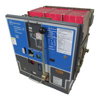
Eaton Cutler-Hammer DS-416 Instructions Manual (93 pages)
Brand:
Eaton
| Category:
Circuit breakers
| Size: 21.43 MB
Table of Contents
Table of Contents
2
Introduction
10
Type DS Breaker Ratings
10
General Description
11
Basic Breaker Assembly
11
Arc Chutes
11
Optional Components
11
Accessories
11
DSL Breakers - Current Limiting Type Breakers and Combinations
11
Special Circuit Breakers: DS-206S and DS-416S
12
Safety Features
13
Recommended Safety Practices
14
Section 1 -Receiving, Handling and Storing
15
Receiving and Handling
15
Storing
15
Weights: Circuit Breakers and Fuse Trucks
15
Approximate Weights
15
Section 2 -First Removal of Breaker from Compartment
16
General
16
Setting the Rails in Front of the Compartment
16
Removing Shipping Brace
16
The Type DS Low Voltage Power Circuit Breaker Is Shipped Inside Its Own Compartment
16
Lifting the Breaker
17
Levering Device Crank Handle Installed
17
Use of Breaker Lifting Adapter
17
Section 3 -Preliminary Examination of Circuit Breaker
18
General
18
View Showing Controls on the Panel
18
Left Side of Breaker with Levering Device Arm in REMOVE Position
19
DS 416 Breaker with Front Panel Removed
19
Right Side Showing Levering Device Arm in TEST Position
19
Rear View Showing Levering Device Arm in CONNECT Position
19
Independent Manual and Power-Operated Breakers
20
Closing Facilities
20
Tripping Facilities
20
Levering Device
20
Section 4 -Basic Operating Instructions
21
General
21
Levering Device
21
Charge the Closing Springs
21
Method Used to Press Trip Plate and Lower Shutter with One Hand, Preparatory to Inserting Crank
21
Close the Breaker
22
Open the Breaker
22
Place the Breaker in the Test Position
23
Place the Breaker in the Connect Position
23
Remove the Breaker for Final Inspection
23
Final Inspection
23
Amptector Trip Settings
23
Place the Breaker in Service
23
Rear of Power-Operated Mechanism
24
Section 5 -Description and Explanation of Operation
24
General
24
The Operating Mechanism and How It Works
24
Rear View of Mechanism (Left Close Spring Removed)
25
Power-Operated Mechanism
25
Explanation of Spring-Charging Mechanism for Power-Operated Breakers
25
Power Operation
26
Front View Showing Major Parts of the Crank Shaft Assembly
27
Power-Operated Spring-Charge Details
28
Crank Shaft Assembly of Power-Operated Mechanism
29
Emergency Spring-Charge on Power Operated Mechanism
29
Standard Schematic and Connection Diagrams for Power-Operated Breakers
30
Spring-Charging Mechanism on Manual Operated Breakers
32
Manual-Operated Mechanisms
32
Explanation of Spring-Charging Mechanism for Manually-Operated Breakers
32
These Sketches Show the Four Basic Positions of Breaker and Linkage with Enlarged View of Trip Shaft and Latch
33
Shunt Trip Details Showing Trip Shaft Adjustment
34
Circuit Breaker Closing Mechanism
34
Circuit Breaker Tripping or Opening Mechanism
35
Miscellaneous Details
36
DS-632 Breaker with Front Panel Removed
36
Front View Showing Close Bar Guard
37
Rear View Showing the Seismic Positioner
37
Mechanical Interlocking, Description and Explanation of Operation
38
Drawout Unit Position Indicator
38
The REMOVE Position
39
The DISCONNECT Position
39
The TEST Position
39
The CONNECT Position
40
Detailed Explanation of Mechanical Interlock System
40
Spring Discharge Interlock
41
Relation of Shutter, Trip Plate, and Trip Shaft
41
Relation of Shutter, Interlock Cam and Levering Device Arms
42
Connected Breaker Manual Close Interlock
43
Close-Release Interlock to Discharge Springs on Levering out of Compartment and Conn. Position no Manual Close Interlock
43
Breaker Equipped for Electric Lockout
44
Closed Breaker Interlock
45
Padlocking Provision
45
Padlock Device - Locked Trip Free and Shutter Raised
45
Section 6 -Circuit Breaker Pole Units, Description and Operation
46
General
46
Moving Contact Sub-Assemblies
46
Three-Pole Assembly of DS-206 Pole Units on Frame
47
Three-Pole Assembly of DS-416 and DS-420 Pole Units on Frame
47
Stationary Contact Sub-Assemblies
48
Three-Pole Assembly of DS-632 Pole Units on Frame
48
Three Pole Assembly of DS-840 Pole Units on Frame
49
Type DS-206 Pole Unit Assembly - Front View
50
Type DS-420 Pole Unit Assembly - Front View
52
Type DS-420 Pole Unit Assembly - Rear View
52
Type DS-632 Pole Unit Assembly - Front View
53
Type DS-632 Pole Unit Assembly - Rear View
53
Type DS-840 Pole Unit Assembly - Front View
53
Type DS-840 Pole Unit Assembly - Rear View
53
Moving and Stationary Contact Details DS-416
55
Moving Contact Details DS-632
57
Moving Contact Details DS-840
59
Breaker with Barrier Removed to Show Mounting of Arc Chutes
61
DS-206 Arc Chute with Details
61
DS-632 Arc Chute with Details
61
Section 7 -Arc Chute
61
General
61
DS-840 Arc Chute with Details
62
Schematic Illustration of Tripping System
63
Section 8 -Circuit Breaker Automatic Tripping System
63
General
63
The Amptector II-A Trip Unit
64
Optional Amptector I-A Solid-State Trip Unit
65
The Amptector I-A Trip Unit
65
Amptector I-A Trip Unit with Front Cover Removed
66
Ground Fault Protection
69
Making Current Release (Discriminator)
69
Servicing of Amptector Trip Unit
70
Actuator
70
Sensors
70
DS-840 Breaker with Front Panel Removed
71
DS-840 Breaker Rear View Showing Sensors
71
Undervoltage Trip Attachment
72
Overcurrent Trip Switch
72
Optional Accessories
71
Frame Size and Sensor Ratings
71
Undervoltage Trip Device
72
Undervoltage Trip Device Operation
72
High Load Switch (Available with Amptector I-A Only)
73
Overcurrent Trip Switch
73
High Load Switch
73
Latch Check Switch
74
Auxiliary Switches
74
Trip Actuator
74
Latch Check Switch Operation
74
Auxiliary Switch Construction Details
74
Amptector Trip Unit Test Kit
75
General
75
Description
75
Operation
75
Test Kit in Operation
76
DSL-206 Breaker Side View
77
Sensor and Limiter Ratings
77
Section 9 -DSL Circuit Breakers and Fuse Trucks
77
General
77
DSL Current Limiters
77
Blown Limiter Indicator
77
DSL-206 Breaker Front View (DSL-416 Similar)
78
DSL-416 Breaker Side View
78
Replacing Fuses
79
Blown Fuse Indicator
79
Fuse Trucks
78
Installing Fuse Trucks
78
Blown Limiter Indicator
79
DS-3200 Fuse Truck Front View
79
DS-3200 Fuse Truck with Front Cover Removed
80
Section 10 -Fixed Breakers
81
General
81
Section 11 -Drawout Dummy Elements
81
Section 12 -Inspection and Maintenance
82
General
82
Contacts and Their Adjustment, DS-206 Breaker
82
When to Inspect
83
Contacts and Their Adjustment, DS-632 Breaker
84
Whatto Inspect
84
Contacts and Their Adjustment, DS-840 Breaker
85
DS-206, DS-206S, DS-416, DS-416S and DS-420
85
Open Position Stop and Anti-Rebound Latch
86
DS-632 and DS-840
86
Replacement of Contacts
86
Ds-206
86
DS-416, DS-416S, DS-420, DS-632 and DS-840
86
Arc Chutes
86
General Inspection
86
Power Operated Mechanisms
86
Levering Mechanism
87
Factory Adjustments
87
Lubrication Points on Left Side of Mechanism
88
Trip Latch Overlap
88
Breaker Open Position Stop (DS-632 Only)
88
Moving Contact Adjustment
88
Levering Mechanism
88
Lubrication Points on Right Side of Mechanism
89
Lubrication
89
Frequency
89
Location and Lubricant
89
Section 13 -Renewal Parts
90
General
90
Identifying Parts for DS-416S and DS-206S
90
DS-416S Parts
90
DS-206S Parts
90
Advertisement
Advertisement
Related Products
Eaton Cutler-Hammer VCP-WR Series
Eaton Cutler-Hammer RED LINE Series
Eaton Cutler-Hammer VCP-WRC Series
Eaton Cutler-Hammer VCP-WRG Series
Eaton Cutler-Hammer VCP-WRGC Series
Eaton Cutler-Hammer VCP-WR Series 18
Eaton Cutler-Hammer VCP-WR Series 20
Eaton Cutler-Hammer 50 VCP-WR 350
Eaton Cutler-Hammer 150 VCP-WR 500
Eaton Cutler-Hammer 150 VCP-WR 750
Eaton Categories
UPS
Circuit breakers
Switch
Industrial Equipment
Industrial Electrical
More Eaton Manuals
Login
Sign In
OR
Sign in with Facebook
Sign in with Google
Upload manual
Upload from disk
Upload from URL