Sign In
Upload
Manuals
Brands
DYNACO Manuals
Amplifier
SCA-80Q
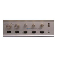
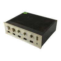
User Manuals: DYNACO SCA-80Q Integrated Amplifier
Manuals and User Guides for DYNACO SCA-80Q Integrated Amplifier. We have
3
DYNACO SCA-80Q Integrated Amplifier manuals available for free PDF download: Assembly Manual, Manual
DYNACO SCA-80Q Assembly Manual (36 pages)
Amplifier and Power Supply Upgrade
Brand:
DYNACO
| Category:
Amplifier
| Size: 4.14 MB
Table of Contents
Table of Contents
2
Table of Figures
3
Section 1: about this Manual
4
Helpful Tools
4
Project Overview
4
Tools You'll Need
4
Who Should Attempt this Project
4
About Components
5
Important Safety Notes
5
Recommended Solder
5
Warranty
5
Figure 1-Empty the Power Supply Components into a Soup Bowl
6
Component Order
7
Figure 2-Silk Screen Shows Power Supply Component Locations
7
Install the Resistors
7
Install the Diodes
8
Figure 3-Pin 1 of the Opto-Isolator Is Indicated by the Dot and the Ridge in the Package
9
Figure 4-Although more Subtle, Notice that the Q4 Has a Square Side and a Round Side
9
Install the Optoisolator
9
Fasten the Mounting Brackets to the PCB
10
Figure 5-Installing the Mounting Brackets on the Power Supply PCB
10
Install the C9 Connection Wires
10
Install the Electrolytic (Polarized) Capacitors
10
Install the Small Non-Polar Capacitors
10
Install the Transistors
10
Check Your Work
11
Disconnect the Old Power Supply and Power Amplifier
11
Sca80Q
12
SCA80 Directions
13
Removing the Amplifier Modules, All Versions
13
Install the RLYDRV Wire
11
Install the New Power Supply
15
Test the New Power Supply
16
Section 2: Kit Building Hints
6
Section 3: Building the Power Supply
6
Figure 6-Grounding Arrangement for Speaker Common Connections on the SCA-80
16
Section 4: Building the Stereo Amplifier Module
16
Figure 7-Component Locations for the Stereo Amplifier Module
17
Install the Diodes
18
Figure 8-Anode Is the Longer of the Two Leads
19
Install the Electrolytic (Polarized) Capacitors
19
Install the Small Non-Polar Capacitors
19
Fasten the PCB to the Heatsink
20
Figure 9-Assembling the PCB to the Heatsink
20
Install the LM3886 Power Amplifier Ics
20
Install the Relays
20
Install the Transistors
20
Build and Install the Inductor Resistor Combination
21
Figure 10-Assembled Amplifier on Main Heatsink
21
Install the Auxiliary Heatsink
24
Install the Bonded Pair Capacitor Wires
24
Install the Red/Black Zipcord Power Wires
24
Figure 11-Assembled PCB with both Heatsinks Attached
25
Install the Power Amplifier
25
Test Your Work
26
Bare Amplifier Tests
26
Amplifier Plus Speaker Tests
26
Amplifier Plus Speaker Plus Source Tests
27
Final Assembly
27
In Case of Trouble
27
About the Design
28
Power Supply Theory of Operation
28
Figure 12-Power Supply Snippet
29
Figure 13-DC Good Detector Snippet
30
Figure 14-AC Detect Snippet
31
Amplifier Board Theory of Operation
32
Figure 15-Power Supply Schematic
34
Figure 16-Page 1 of Amplifier Board Schematic
35
Figure 17-Page 2 of Amplifier Board Schematic
36
Advertisement
DYNACO SCA-80Q Assembly Manual (15 pages)
C11 REPLACEMENT
Brand:
DYNACO
| Category:
Amplifier
| Size: 1.31 MB
Table of Contents
Table of Contents
2
Table of Figures
2
Section 1: about this Manual
3
Other SCA-80 Upgrades
3
Who Should Attempt These Projects
3
Tools You'll Need
3
Project Overview
4
About Components
4
Recommended Solder
4
Section 2: Building the Power Supply PC Board
5
First, Get a Soup Bowl
5
Install the Resistors
5
Figure 1-A Soup Bowl Makes Assembly Easy
5
Figure 2-Guide to Component Installation
6
Resistor Notes
7
Install the Diode
7
Install U2, the TO-92 Package 17.5 Volt Regulator
7
Figure 3-17.5 Volt Regulator Comes in TO-92 Package
7
Install the 24 Volt Regulator, TO-220 Package
8
Figure 4-Front and Back Views of Q6 Mounted on Heat Sink
8
Install the Capacitors
9
Solder GJ1 in Place
9
Remove the Old Power Supply
9
Figure 5-Remove These Wires from C11
9
Install the New Power Supply
10
Figure 6-Mounting the Power Supply to the SCA80
10
Figure 7-Showing Location of C11
11
Connect the New Power Supply
12
Final Test and Assembly
12
Figure 8-New Power Supply Installed in SCA80(Q)
13
Figure 9-Close up of Assembled Circuit Board
13
Schematic
14
Figure 10-Schematic of C11 Replacement Electronically Regulated Power Supply for
14
Figure 11-Demonstrating the Resistor Color Code
15
Resistor Color Code
15
DYNACO SCA-80Q Manual (12 pages)
C9 REPLACEMENT
Brand:
DYNACO
| Category:
Amplifier
| Size: 2.09 MB
Table of Contents
Table of Contents
2
Section 1: about this Manual
3
Who Should Attempt this Project
3
Tools You'll Need
3
Project Overview
3
Important Safety Notes
4
Section 2: Preliminaries
4
Opening the Amplifier
4
Check the Power Supply Voltage
4
Figure 1-Side and Back Views Showing Location of Cover Retaining Screws
4
Building the Dynamite Capacitor
5
Figure 2-Triple Cap Installed into the Capacitor Clamp
5
Removing C9
5
Figure 3-Ground Harness Configuration
6
Figure 4-Soldering the Ground and Positive Harnesses on the New C9 Dynamite Capacitor Arrangement
6
Installing the New C9 into the Amplifier
7
Figure 5-Note the Orientation of the Capacitor Assembly When Installed into the Amplifier
7
Figure 6-Reconnecting the Wires to the New C9
7
Figure 7-Stock Amplifier Layout (before C9 Replacement)
9
Figure 8-Stock Amplifier with Dynamite Capacitor Configuration Installed
10
Check and Test Your Work
11
Reassemble the Amplifier
11
Results
11
References
11
Wire Splicing Using Heat Shrink Tubing
12
Appendix 1
12
Advertisement
Advertisement
Related Products
DYNACO SCA-80
DYNACO Dynakit ST35
DYNACO ST-70
DYNACO ST400RCAJ
DYNACO Slimline Series
DYNACO MARK VI
DYNACO PAS-2
Dynaco PAS-4
DYNACO PAT-4
DYNACO PAT-5
DYNACO Categories
Amplifier
Tuner
Gate Opener
Controller
Power Supply
More DYNACO Manuals
Login
Sign In
OR
Sign in with Facebook
Sign in with Google
Upload manual
Upload from disk
Upload from URL