Sign In
Upload
Manuals
Brands
DryGair Manuals
Dehumidifier
DG6
DryGair DG6 Manuals
Manuals and User Guides for DryGair DG6. We have
3
DryGair DG6 manuals available for free PDF download: Installation, Operation And Maintenance Manual, Manual
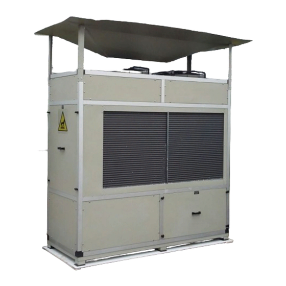
DryGair DG6 Installation, Operation And Maintenance Manual (102 pages)
50 Hz & EU Models Dehumidification Units
Brand:
DryGair
| Category:
Dehumidifier
| Size: 12.33 MB
Table of Contents
Table of Contents
6
Introduction
9
Safety
11
Figure 2-1. Drygair Identification Label
13
Unit Overview
14
Figure 3-1. Drygair Unit (Front View)
16
Figure 3-2. Drygair Unit (Rear View)
16
Installation
17
Figure 4-1. Transferring the Unit
22
Figure 4-2. Compressor Transport Locks after Removal
24
Figure 4-3. Air Distributor Module (4-Way Canopy)
25
Figure 4-4. Water Drain Outlet
27
Figure 4-5. Electrical Switchboard and Electricity Terminal Block
28
Figure 4-6. Hole for Main Power Cable
29
Figure 4-7. Replacing Wire Channel Cover
29
Unit Parts and Components
30
Figure 5-1. Temperature and Humidity Sensor
30
Figure 5-2. Sensor Unit
30
Figure 5-3. Defrost Temperature Sensor
31
Figure 5-4. Electrical Compartment
32
Figure 5-5. Compressor (Front View)
35
Figure 5-6. Compressor (Rear View)
35
Figure 5-7. Oil Pressure Protector and Switches
36
Figure 5-8. Service Compartment (DG-12)
37
Figure 5-9. Expansion Valve
37
Figure 5-10. Service Compartment (DG-12 EU)
38
Figure 5-11. Electronic Expansion Valve (DG-12 EU)
38
Figure 5-12. Sight Glass
39
Figure 5-13. Axial Blowing Fans
39
Unit Operation
40
Figure 6-1. Humidistat Controller
43
Maintaining the Unit
49
Troubleshooting and Repairing the Unit
55
Figure 9-1. Four-Direction Canopy
74
Figure 9-2. Air Distributor Module (4-Way Canopy)
75
Figure 9-3. Side Canopies (Different Orientations)
76
Figure 9-4. Air Distribution Panel
77
Figure 9-5. Air Heating Option
78
Figure 9-6. Temperature Valve Controller
79
Figure 9-7. Drygair Split Unit
81
Figure 9-8. Connecting Copper Tubes (Lower Section)
82
Figure 9-9. Tube Stop Valves - Lower Section (Left) & Upper Section (Right)
83
Figure 9-10. Electrical Cables
85
Figure 9-11. Fan Connections
85
Figure 9-12. Brown Terminal Block (50-56)
86
Figure 9-13. Water Drainage
87
Figure 9-14. Unit with Heating/Cooling
88
Figure 9-15. Climate Control Relays
89
Figure 9-16. Temperature Valve Controller
91
Figure 9-17. Temperature Valve Controller and Serial Communication Card
91
Figure 9-18. Controller Cover Centerpiece
92
Figure 9-19. Communication Card in the Controller
92
Advertisement
DryGair DG6 Installation, Operation And Maintenance Manual (70 pages)
Dehumidification Unit
Brand:
DryGair
| Category:
Dehumidifier
| Size: 1.57 MB
Table of Contents
Table of Contents
3
Introduction
7
Safety
9
Figure 2-1. High Voltage Warning Label
11
Figure 2-2. Hearing Protection Required Label
11
Figure 2-3. Hot Surface Caution Label
11
Figure 2-4. Lift from here Notice
11
Figure 2-5. Drygair Identification Label
12
Unit Overview
13
Figure 3-1. Drygair Unit (Front View)
15
Figure 3-2. Drygair Unit (Rear View)
15
Installation
16
Figure 4-1. Transferring the Unit
25
Positioning the Unit
27
Figure 4-2. Water Drain Outlet
28
Figure 4-3. Electrical Switchboard and Grid Terminal Block
29
Unit Parts and Components
30
Figure 5-1. Temperature and Humidity Sensor
30
Figure 5-2. Sensor Unit
30
Figure 5-3. Defrost Temperature Sensor
31
Figure 5-4. Electrical Compartment
32
Figure 5-5. Compressor (Front View)
35
Figure 5-6. Compressor (Rear View)
35
Figure 5-7. Oil Pressure Protector and Switches
36
Figure 5-8. Heat Exchange Compartment
36
Figure 5-9. Expansion Valve
37
Figure 5-10. Sight Glass
37
Figure 5-11. Blowing Fans
38
Unit Operation
39
Figure 6-1. Humidistat Controller
42
Operating the Unit
44
Maintaining the Unit
46
Annual Maintenance
48
Troubleshooting and Repairing the Unit
49
Appendices
51
Figure 9-1. Standard Unit
52
Figure 9-2. Small Unit
53
Figure 9-3. Standard Split Unit
54
Figure 9-4. Small Split Unit
55
Figure 9-5. Standard Unit with Heating & Cooling
56
Figure 9-6. Small Unit with Heating & Cooling
57
Figure 9-7. Standard Split Unit with Heating & Cooling
58
Figure 9-8. Small Split Unit with Heating & Cooling
59
Figure 9-9. Warm Climate Unit
60
Figure 9-10. Four-Direction Canopy
61
Figure 9-11. Air Distributor Module (4-Way Canopy)
62
Figure 9-12. One-Direction Canopy
63
Figure 9-13. Air Distribution Panel
64
Figure 9-14. Split Unit
65
Figure 9-15. Split Unit Connecting Tubes
65
Figure 9-16. Air Heating Option
67
Comments and Notes
68
DryGair DG6 Manual (46 pages)
Dehumidification Unit Smart DG Interface
Brand:
DryGair
| Category:
Dehumidifier
| Size: 2.57 MB
Table of Contents
Table of Contents
3
1 Introduction
7
Before You Begin
7
Further Information
7
Conventions
8
2 Safety
9
Hazards
9
Operation Safety Notes
10
Maintenance Safety Notes
10
3 Smart DG Overview
11
Figure 1. the C.pco Programmable Controller
11
Figure 2. Smart DG (on Smartphone)
11
The Smart DG Interface
12
4 Smart DG Controller Operations
13
Setting the Controller's Date and Time
13
Figure 3. Electrical Compartment
13
Changing the Setpoint - Offline
15
Converting Temperature Units (°F/°C) - Offline
16
Downloading Data from the Smart DG - Offline
17
Updating the Controller's Software Using a USB
18
5 Smart DG Set-Up Procedure
20
Registering the Units and Creating a Customer Map
20
Activating the Smart-Hub License
21
Assigning the Unit Address
21
Smart-Hub Description
23
Required Parts and Tools
23
Figure 4. Smart-Hub Parts
23
Mounting Options
24
Figure 5. Smart-Hub Mounting
24
Ethernet Cable Connections
25
Figure 6. Smart-Hub Connections
25
Connecting the Power Supply
26
Figure 7. Power Supply and Plugs
26
Figure 8. Smart-Hub Power
26
Technical Specifications and Warnings
27
Connecting the Units to the Internet
28
Connecting the Smart DG Units to the Smart-Hub Controller
28
Figure 9. Cable Routing
28
Connecting Multiple Units
29
Figure 10. Daisy Chain Topology
29
6 Smart DG Online Interface
30
Logging in to the Drygair Online Interface
30
Figure 11. Drygair Homepage
30
Figure 12. Drygair Cloud Login Screen
30
Figure 13. Remote Pro Screen
31
Figure 14. Drygair Cloud Homepage
31
Remote Monitoring and Controlling
32
Available Online Functions in Mode 1 (Local Mode)
33
Available Online Functions in Mode 2 (Remote Mode)
35
Malfunction Alarms
36
7 Appendices
39
Appendix A. Smart-Hub Account Customer and Unit Information Setup
39
Empty Form
39
Filled-Out Form
40
Appendix B. Water Extraction Meter
41
Figure 15. Water Meter
41
Connecting the Water Extraction Meter
42
Figure 16. Installing the Water Meter
42
Figure 17. Installed Water Meter
43
Appendix C. List of Alarm Descriptions
44
Advertisement
Advertisement
Related Products
DryGair DG12
DryGair DG13
DryGair DG5
DryGair DG3
DryGair DG-X
DryGair Categories
Dehumidifier
More DryGair Manuals
Login
Sign In
OR
Sign in with Facebook
Sign in with Google
Upload manual
Upload from disk
Upload from URL