Sign In
Upload
Manuals
Brands
Dräger Manuals
Medical Equipment
Evita 4
Dräger Evita 4 Manuals
Manuals and User Guides for Dräger Evita 4. We have
3
Dräger Evita 4 manuals available for free PDF download: Instructions For Use Manual, Repair Instructions, Short Manual
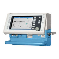
Dräger Evita 4 Instructions For Use Manual (192 pages)
Intensive Care Ventilator. Software 4.n
Brand:
Dräger
| Category:
Medical Equipment
| Size: 2.57 MB
Table of Contents
For BIPAP and SIMV, for Weaning Without Transitions
3
Table of Contents
5
For Your Safety and that of Your Patients
11
Intended Medical Application
13
Operating Concept
15
Structure of the Control Unit
16
On-Screen Controls
17
Without Confirmation
18
Screen Keys for Function Selection, Adjustment and Confirmation
18
Screen Pages
21
Standard Page
22
Adjustment« Screen Page
22
Alarm Limits« Screen Page
24
Measured Values« Screen Page
25
Measurement Manoeuvre« Screen Page
26
Calibration« Screen Page
26
Configuration« Screen Page
27
Positioning the Control Unit
27
Ergonomic Positioning
27
Preparation
29
Attaching Components
30
Fitting Expiration Valve
30
Fitting Flow Sensor
30
Fitting O 2 Sensor Capsule
31
Note on Use of Heat and Moisture Exchanger (HME)
31
Ventilation Adults and Children
32
Connecting Aquapor Humidifier
32
Connecting Ventilation Hoses
32
Fitting Temperature Sensor
33
Fitting CO 2 Cuvette and CO 2 Sensor
34
Ventilating Infants
34
Fitting Bacterial Filter
34
Fitting Humidifier and Ventilation Hose
35
If Using Bacterial Filters
35
Supply and Connections
36
Electrical Power Supply
36
Note on Use of a Socket Strip for Ancillary Equipment
36
Temporary Interruption of Power Supply
36
Gas Supply
37
Evita Remote (Optional)
38
Connection
38
Note Automatic Self-Test
39
Nurse Call (Optional)
40
Technical Data
40
Before Using for the First Time
41
Selecting the Language of the Display Texts
41
Device Check
42
Before Use on Patient
42
Performing Device Check
43
Checking the Hose System for Leaks
46
Positioning the Control Unit
47
To Position the Control Unit on the Wall Rail
47
To Position the Control Unit on the Device
47
Operation
49
Starting up
50
Switching on
50
Patient Mode
50
Selecting the Patient Mode
51
Entering the Ideal Body Weight
51
Select the Previous Settings
51
Starting Ventilation
52
Setting Ventilation Modes
53
Ippv
53
Simv, Simv/Asb
57
Frequency Can be Reduced to
57
Bipap, Bipap/Asb
60
BIPAP Assist
62
Cpap, Cpap/Asb
63
MMV, MMV/Asb
65
Aprv
67
Independent Lung Ventilation ILV
69
Preparation
69
Setting the Master and Slave Device
71
Apnoea Ventilation
76
Setting Alarm Limits
77
In the Event of an Alarm
78
Cancel Alarm Tone
79
Information
79
Displaying Curves and Measured Values
80
Displaying Measured Values
81
Trends
82
Loops
83
Reference Curve Displays
83
Single Stroke Displays
83
Zoom Loops (Optional)
83
Display Loops in the Upper Graphic Area
84
Logbook
85
Screen Freeze
86
Special Functions
87
Manual Inspiration
87
Exspiration Hold
87
Medicament Nebulisation
88
Oxygen Enrichment for Bronchial Suction
91
Special Measurement Procedure: Intrinsic PEEP
93
Special Measurement Procedure: Occlusion Pressure P 0.1
94
Shut-Down
95
Selecting Standby Mode
96
Quitting Standby Mode
96
Selecting/Quitting Standby Mode
96
Calibration
97
Calibrating O 2 Sensor
97
Calibrating Flow Sensor
98
External Flow Source
99
Checking/Calibrating CO 2 Sensor
100
CO 2 Zero Checking
100
Testing CO 2 Calibration with Test Filter
102
Testing CO 2 Calibration with Test Gas
103
Calibrating CO Sensor
105
Calibrating CO 2 Sensor
105
Resetting CO 2 Calibration
106
Configuration
107
Sound
108
Adjusting the Volume of the Alarm Tone
108
Screen
109
Selecting Displayed Measured Values
109
Selecting Displayed Curves
111
Selecting Displayed Trends
112
Ventilation
113
Selecting Ventilation Modes
113
Selecting Pmax Pressure Limit
115
Selecting Autoflow ® as Start-Up Ventilation Mode
116
Apnoea Ventilation On/Off
117
Selecting Patient Mode
118
Start-Up Values for Ventilation Parameters and Alarm Limits
119
Setting Start-Up Values for Ventilation Parameters »V T , F
119
Setting Start-Up Values for Ventilation Parameters »Pressure, O 2 , I:E
119
Setting Start-Up Values for Ventilation Parameters »Pressure, O 2 , I:E
121
Leakage Compensation On/Off
122
Setting Start-Up Values for Alarm Limits
123
System Defaults
124
Setting External Interface
124
Setting Time and Date
125
Setting Language and Units
125
Service Diagnosis
126
Troubleshooting
127
Preparing
135
Dismantling
136
CO 2 Sensor (Optional)
136
Temperature Sensor
136
Medicament Nebuliser
137
Ventilation Hoses
137
Flow Sensor
137
Expiration Valve
138
Humidifier
138
Disinfecting/Cleaning
139
Assembling
142
Fitting Expiration Valve
142
Before Reusing on Patient
143
Maintenance Intervals
143
Clean or Replace Cooling Air Filter
144
Disposing of Batteries and O 2 Sensors
144
Removing/Fitting Ambient Air Filter
144
Replacing Cooling Filter
144
Correct Disposal of Apparatus
145
What's What
147
Control Unit
148
Front Connections
149
Back Panel
150
Technical Data
151
Environmental Conditions
152
Settings
152
Performance Data
153
Measured Value Displays
153
Monitoring
156
Operating Data
157
Machine Outputs
157
Electromagnetic Compatibility (EMC)
158
Classification
158
UMDNS-Code
158
Materials Used
158
Description
159
Ventilation Modes
160
Volume-Controlled Ventilation with PLV and Autoflow
160
Classic Volume Constant Mandatory Ventilation Stroke
160
Manual Pressure Limiting with Pmax
160
Autoflow
161
Start-Up Procedure with Autoflow
162
Sigh
163
Simv
164
Asb
165
Bipap
166
BIPAP Assist
167
Aprv
168
MMV
168
Flow Measurement
170
Compensation of the Effect of Hose System Compliance
170
Conversion According to Ambient Conditions
170
Automatic Leakage Compensation
172
Weaning Parameters
174
Occlusion Pressure P 0.1
174
Rapid Shallow Breathing RSB
175
Negative Inspiratory Force NIF
175
Intrinsic PEEP
176
Insp. O 2 Concentration During Medicament Nebulisation
177
Abbreviations
178
Symbols
181
Bibliography
182
Parts List
183
Order List
185
What was New in Evita 4 Software 2.N
187
What was New in Evita 4 Software 3.N
188
Index
189
Advertisement
Dräger Evita 4 Repair Instructions (89 pages)
Brand:
Dräger
| Category:
Medical Equipment
| Size: 0.8 MB
Table of Contents
Table of Contents
1
10 Graphics Controller PCB Evita
4
1 Power Supply Unit
6
Output Voltages
6
Sub D Socket Configuration
7
Voltage Measurement
8
Replacing the Power Supply Unit
9
Retrofitting the Optional DC Module
11
Replacing the Optional Rechargeable Battery
16
2 Cpu 68332 Pcb
18
Power Supply to the CPU 68332 PCB
18
Service Leds on the CPU 68332 PCB
20
Replacing the Battery on the CPU 68332 PCB
21
Replacing the Real-Time Clock on the CPU 68332 PCB
22
Replacing the CPU 68332 PCB
23
Test Possible in DS Mode
24
Diagnosis Mode
24
External DS Mode Using PC
24
Conversions
25
Retrofitting of CPU 68332 PCB as Per IDM No. 6
25
3 Communication PCB (Optional)
26
Power Supply to the Communication PCB
26
Communication PCB Connector Pin Assignment
26
Replacing the Communication PCB
29
Tests Possible in DS Mode
30
Diagnosis Mode
30
External DS Mode Using PC
30
4 Paediatric Flow PCB Option for Evita 4 as of SW
31
Power Supply to the Paediatric Flow PCB
31
Connector Pin Assignment of the Paediatric Flow PCB
31
Replacing the Paediatric Flow PCB
33
5 CO2 Carrier PCB
34
CO2 Carrier PCB Connector Pin Assignment
35
Replacing the CO2 Carrier PCB
38
Tests Possible in DS Mode
38
Diagnosis Mode
38
External DS Mode Using PC
38
Conversions
39
Replacing CO2 Carrier PCB According to IDM No. 3 (Evita 4)
39
Conversion Due to Error Message "Ext. Battery Reversed Poles" IDM No. 2 (Evita 2 Dura) or IDM No. 19 (Evita 4)
40
Conversion for Device Error 02.71.003 IDM No. 2 (Evita 2 Dura) or IDM
41
6 Power Supply PCB (CO 2 Measurement)
42
Power Supply to the Power Supply PCB
42
Connector Pin Assignment on the Power Supply PCB
42
Measuring the Voltages on the Power Supply PCB
43
Printed Circuit Board on Extender Board
43
Printed Circuit Board in the Evita
43
Test Points on the Power Supply PCB
44
Replacing the Power Supply PCB
45
7 Processor Board PCB (CO 2 Measurement)
46
Power Supply to the Processor Board PCB
46
Connector Pin Assignment of the Processor Board PCB
46
Replacing the Processor Board PCB
48
8 CO2 Measurement
49
Fault Diagnosis Chart
49
CO2 Sensor
50
9 Spo2 Module (Optional)
51
Power Supply to the Graphics Controller PCB
52
Connector Pin Assignment of the Graphics Controller PCB
52
Replacing the Graphics Controller PCB
57
Tests Possible in DS Mode
58
Diagnosis Mode
58
10.4.2 External DS Mode Using PC
58
11 Display with DC/AC Converter for Backlighting Evita
59
Power Supply to the Display
60
Connector Pin Assignment of the Display
60
Replacing the Display
61
Testing DC/AC Converter for Backlighting
63
Tests Possible in DS Mode
63
Diagnosis Mode
63
External DS Mode Using PC
63
12 Backlighting Evita 4
64
Toshiba Display (1995 or Later), Version 1
64
Power Supply to the Backlighting
64
Replacing the Backlighting
65
NEC Display (1996 or Later), Version 2
66
Sharp Display (1996 or Later), Version 3
66
Toshiba Display (1997 or Later), Version 0
66
13 Touchscreen/Window Evita 4
67
Power Supply to the Touchscreens
67
Replacing the Touchframe
68
Tests Possible in DS Mode
69
Diagnosis Mode
69
External DS Mode Using PC
69
Replacing the Window
69
7 Segment PCB Evita 2 Dura
71
Voltage Supply to the 7-Segment PCB
71
X1 Connector on the 7-Segment PCB
71
7-Segment PCB Repair Information
71
7-Segment PCB Component Layout Diagram
72
15 Frontpanel PCB Evita 2 Dura
73
Voltage Supply to the Frontpanel PCB
73
X1 Connector on the Frontpanel PCB to the Electronics
73
Voltage Supply to Peripheral Equipment
73
X2 Connector on the Frontpanel PCB to the 7-Segment PCB
73
X3 Connector on the Frontpanel PCB to the Membrane Keyboard
73
X5 Connector on the Frontpanel PCB to the Control Knob
74
X7 Connector on the Frontpanel PCB to the Display
74
X9 Connector on the Frontpanel PCB to the DC/AC Transformer
74
Front Panel PCB Repair Information
74
Frontpanel PCB Component Layout Diagram
75
16 Pneumatics Controller PCB
76
Power Supply to the Pneumatics Controller PCB
76
Connector Pin Assignment of the Pneumatics Controller PCB
76
Replacing the Pneumatics Controller PCB
84
Tests Possible in DS Mode
85
Diagnosis Mode
85
16.4.2 External DS Mode Using PC
85
17 HPSV Controller PCB
86
Power Supply to the HPSV Controller PCB
86
Replacing the HPSV Controller O
88
Air Pcb
88
Notes Relating to Trouble Shooting
89
Tests Possible in DS Mode
89
Diagnosis Mode
89
External DS Mode Using PC
89
Dräger Evita 4 Short Manual (35 pages)
Brand:
Dräger
| Category:
Medical Equipment
| Size: 0.91 MB
Advertisement
Advertisement
Related Products
Dräger Evita V Series
Dräger Evita 2 Dura
Dräger EVITA XL
Dräger Evita 2 dura Ventilation Plus
Dräger Evita 2
Dräger EBS
Dräger MSI EM200plus-i
Dräger EM200-E
Dräger DOB EAN 200
Dräger 105029
Dräger Categories
Medical Equipment
Respiratory Product
Measuring Instruments
Test Equipment
Gas Detectors
More Dräger Manuals
Login
Sign In
OR
Sign in with Facebook
Sign in with Google
Upload manual
Upload from disk
Upload from URL