Sign In
Upload
Manuals
Brands
Dodge Manuals
Trucks
D350 1990
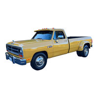
User Manuals: Dodge D350 1990 Pickup
Manuals and User Guides for Dodge D350 1990 Pickup. We have
2
Dodge D350 1990 Pickup manuals available for free PDF download: Service Manual
Dodge D350 1990 Service Manual (1135 pages)
Rear wheel drive ram truck
Brand:
Dodge
| Category:
Trucks
| Size: 64.96 MB
Table of Contents
Component and System Index
4
Group Title
6
Vehicle and Component Identification
7
Vehicle Code
7
Vehicle Identification Number
7
Equipment Identification Plate
7
Equipment Identification Label
8
Vehicle Safety Certification Label
8
Body Code Plate
8
Engine Serial Number
9
Transmission Identification
9
Body Code Plate Information
9
Engine Serial Number 5.2L and 5.9L
9
Power Team Availability
10
RAM Pickup
10
RAM Chassis Cab
11
Ramcharger Sport Utility
11
Standard Truck Body Dimensions
14
Torque References
15
Bolt Torque
15
Grade 5 and 8 Standard Torque Specifications
15
Metric Bolt Identification
15
International Symbols
16
Metric System
16
Metric Prefixes
16
Conversion Tables
17
Lubrication and Maintenance
20
General Information
20
Severe Service
20
Noise Control Systems
20
Required Maintenance for Noise Control Systems
21
Exhaust System
21
Air Cleaner Assembly
21
Tampering with Noise Control System Prohibited
21
Gear Lubricants
22
Lubricants/Greases
22
Parts and Lubrication Recommendations
22
Light Duty Cycle - Gasoline Engines
23
Heavy Duty Cycle - Gasoline Engines
24
Fluid Capacities
27
Assist (Jump) Starting
27
Booster Battery
27
Connecting Positive Jumper Cable
27
Hoisting Recommendations
28
Portable Starting Unit
28
Twin Post
28
Floor Jack
28
Towing Recommendations
29
Single Post Hoist/Outboard Twin Post
29
Hoisting
29
Towing Equipment
29
Lifting-Ground Clearance
30
Rear Towing Pickup
30
Front Towing Pickup
30
Towing Chains and Hooks
30
Flat Towing
31
Ignition Key Available
31
Ignition Key Not Available
31
Safety Precautions
31
Storage for Less than 1 Month
32
Storage for 1 to 3 Months
32
Storage for more than 3 Months
32
Engine
33
During Break-In
33
Viscosity
33
Energy Conserving
33
Checking Engine Oil Level
34
Materials Added to Engine Oils
34
Engine Oil Filter Selection
34
Engine Oil Filter
34
Cooling System
35
Hoses and Fittings
35
Radiator Cap
35
Engine Air Cleaner
35
Manifold Heat Control Valve
36
Air Injection System
36
Crankcase Ventilation System
36
Ventilation System Operation
36
Frequency of Service
37
Inspection and Service Procedure
37
Crankcase Inlet Air Filter
37
Check Vacuum at PCV Valve
37
Fuel System
38
Gasolines Containing Alcohol
38
Gasolines Containing MTBE
38
Materials Added to Fuel
38
Spark Plugs
39
Ignition Timing
39
Battery
39
Hoses
39
Drive Belts
40
Engine Mounts
40
Ignition Wires
40
Air Conditioning Compressor
40
Drivetrain
41
Clutch and Brake Linkage
41
Clutch Master Cylinder
41
Shifter Mechanism Boot
41
Check Fluid Level
42
Special Additives
42
Drain and Fill
42
Gearshift Linkage
42
Automatic Transmission
43
Transfer Case
43
Drain, Filter Change, Band Adjustment and Fill
43
Lubricant Selection
44
Gear Shift Mechanism
44
Conventional Differential
44
Frequency of Oil Change
44
Front Axle Universal Drive Joint and Pivot Bearings
45
Propeller Shaft Universal Joints
45
Removing Filler Plug
45
Rear Axle Fill Plugs
45
Universal Joint Seal Inspection
46
Universal Joint and Slip Spline with Grease Fittings (Typical)
46
Constant Velocity Universal Joint Lubrication Points
46
Chassis and Body
47
Steering Linkage
47
Front Suspension Ball Joints
47
Steering Linkage Lubrication
47
Manual Steering Gear
48
Power Steering
48
Wheel Bearings
48
Front Wheel Bearings
48
Upper and Lower Control Arm Bushings
49
Brakes
49
Master Cylinder
49
Check Master Cylinder Fluid Level
49
Parking Brake
50
Brake Hoses
50
Headlights
50
Speedometer Cable
50
Body Mechanisms Lubrication
51
Accessories
52
Snow Plow
52
Snow Plow Components
52
Hydraulic Cylinder and Motor
53
Solenoid Valves
53
Mechanical Hydraulic Valves
53
Solenoid Valve "B"
53
Pilot Check Valve
54
Crossover Relief Valve
54
Raise Blade—Voltage Application & Hydraulic Fluid Flow
55
Lower & Float Blade - Voltage Application & Hydraulic Fluid Flow
56
Angle Blade Right - Voltage Application & Hydraulic Fluid Flow
57
Angle Blade Left— Voltage Application & Hydraulic Fluid Flow
58
Snow Plow Diagnosis
59
Snow Plow Wiring Diagrams
60
Service Procedures
60
Solenoid Valve Coil Functional Test
60
Snow Plow Control Wiring Diagram
61
Snow Plow Auxiliary Lighting Wiring Diagram
63
Power Unit - Exploded View
64
Power Unit Disassembly/Inspection
65
Cylinder Components
65
Power Unit Assembly
66
Insert Valve
66
Solenoid Valve "C"/Four-Way Valve
66
Crossover Relief Valve - Disassembled
66
Power Angling Cylinder Service
67
Angling Cylinder - Exploded View
67
Snow Plow Specifications
68
Torque Specifications
68
Front Suspension
70
Front Wheel Alignment
72
General Alignment Information
72
Wheel Alignment Measurements
72
Pre-Alignment Inspection
73
Caster & Camber Adjustment Location
73
Front Suspension Diagnosis
74
Wheel Alignment Measurements/Adjustments
75
Wheel "Toe" Position
75
"Toe" Position Adjustment
75
Front Suspension Component Service
76
Lower Suspension Arm Strut Removal/Installation
76
Lower Suspension Arm Removal/Installation
76
Coil Spring Suspension—2Wd
77
Spring Compressor & Ball Stud Loosening Tools Installed
77
Lower Ball Stud Replacement
78
Lower Ball Stud Removal
79
Lower Ball Stud Installation
79
Lower Suspension Arm Bushing Replacement
80
Upper Suspension Arm Removal/Installation
80
Ball Stud Loosening Tool Installed
80
Upper Suspension Arm Bushing Replacement
81
Upper Ball Stud Replacement
81
Upper Suspension Arm Bushing Removal
81
Steering Knuckle Removal/Installation
82
Upper Suspension Arm Bushing Installation
82
Tie-Rod End Ball Stud Removal
82
Loosening Upper Ball Stud
83
Model 44 Front Axle Service -4WD Vahicles
84
Rotor/Hub and Bearing Service
84
Steering Knuckle, Spindle and Ball Stud Service
85
Wheel Bearing Nut Lock Removal
85
Wheel Bearing Adjusting Nut, Retaining Washer & Nut Lock
85
Spindle Removal from Steering Knuckle
86
Needle Bearing Removal (Right-Side Spindle)
86
"Snap" Retaining Ring Removal/Installation
86
Seal Installation on Axle Shaft Shield
88
Lubricating Seal
88
Right Axle Shaft Removal/Installation
89
U-Joint Service
89
Left Axle Shaft Service
90
Bearing Cap Removal
90
Bearing Cap Installation
90
Bearing Cap & Spider Installation
90
Left (Disconnect) Axle
91
Intermediate Shaft Bearing Removal
91
Right (Disconnect) Axle Housing Service Tools
91
Inner Axle Shaft Removal/Installation
92
Intermediate Shaft Bearing Installation
92
Sealant on Housing Cover
93
Wheel Lug Nut Tightening Sequence
93
Disconnect Axle Vacuum Control System Service
94
Axle Shift Motor Functional
94
Disconnect Axle Vacuum Control System
94
Axle Vacuum Shift Motor
94
Disconnect Axle/Shift Motor Diagnosis
95
Two-Wheel Drive Operation Diagnosis
95
Four-Wheel Drive Operation Diagnosis
96
Disconnect Axle Vacuum Hose Routing
97
Shift Motor Service
98
Steering Knuckle Arm Removal/Installation
98
Shift Motor & Axle Disconnect Components
98
Drag-Link Ball Stud Removal with Tool C-4150
98
Drag Link Removal/Installation
99
Tie-Rod End Replacement
99
Steering Knuckle Arm Removal
99
Correct Drag Link Installation
99
Stabilizer Bar Removal/Installation
100
Complete Axle Removal/Installation
100
Tie-Rod End Removal
100
Stabilizer Bar—4Wd Vehicles
100
Differential Service
101
Ring Gear Runout Measurement
102
Bearing Cap Identification
102
Differential Housing Separation
102
Differential Case Flange "Runout" Measurement
103
Drive Pinion Gear Shaft Yoke Nut Removal
103
Drive Pinion Gear Shaft Yoke Removal
103
Model 44 Axle Differential - Exploded View
104
Inner Bearing Removal
104
Pinion Gear Mate Shaft Lock Pin Removal
105
Differential Bearing Removal
105
Master Bearing Tools on Hubs
106
Drive Pinion Gear Depth Information
107
Differential Case "End Play" Measurement
107
Drive Pinion Gear ID Numbers
107
Drive Pinion Gear Standard Depth/Distance
108
Shim Locations
108
Drive Pinion Gear Depth Variance
109
Drive Pinion Gear Depth Measurement
109
Pinion Gear Depth Gauge Tool Set D-271
109
Pinion Block Tool Inserted in Shaft Bore
109
Arbor Disc & Arbor Tools in Housing
110
Pinion Height Block Tool against Arbor Tool
110
Shaft Front Bearing Cup Installation
110
Shaft Rear Bearing Installation
111
Rotating Drive Pinion Gear Shaft
111
Drive Pinion Gear Shaft Seal Installation
112
Ring Gear "Backlash" Adjustment
114
Differential Housing, Separation
115
Ring Gear "Backlash" Measurement
115
Ring Gear Teeth Contact Patterns
116
Differential Bearing Installation
116
Differential Bearing Cap Reference Letters
116
Desired Teeth Contact Patterns
117
Incorrect Teeth Contact Patterns
118
Lubricant
119
Drain and Refill
119
Model 60 Front Axle Service—4Wd
120
Dualmatic Locking Hub Service
120
Wheel Bearing Adjustment
121
Rotor/Hub and Wheel Bearing Service
121
Hex-Head Screw Removal/Installation
122
Caliper Lock & Spring Removal
122
Axle Shaft and U-Joint Service
123
Caliper Lock & Spring Installation
123
Spindle & Splash Shield Removal/Installation
123
Steering Knuckle Service
125
Lower Ball Socket Removal
126
Seal & Lower Bearing Cup Installation
126
Lower Bearing & Seal Installation
126
Axle Specifications
150
Rear Axles
152
Noise Diagnosis
153
Tire Noise
154
Front Wheel Bearing Noise
154
Gear Noise (Drive Pinion and Ring)
154
Bearing Noise
154
Pre-Disassembly Inspection
155
Driveline "Snap"
155
Axle Shaft Bearing Noise
155
Engine and Transmission Noise
155
Rear Axle Alignment
159
Tire/Wheel Balance
159
Sure-Grip/Trac-Lok Differentials
160
Rear Axle with 8 3/8-Inch Ring Gear
161
Rear Axle with 9 1/4-Inch Ring Gear
162
Axle Shaft, Seal and Bearing Service
163
Axle Shaft Removal
163
Pinion Gear Mate Shaft Lock Screw
163
Axle Shaft C-Clip Lock
163
Axle Shaft Seal and Bearing Removal
164
Axle Shaft Bearing and Seal Installation
164
Axle Shaft Installation
164
Axle Shaft Seal Installation
164
Drive Pinion Gear Shaft Seal Replacement
165
Tightening Drive Pinion Gear Shaft Nut
166
Standard Differential Service
167
Differential "Side Play" Test
168
Brake Components
210
Antilock Rear Wheel Brake System (Rwal)
210
Brake Fluid/Lubricants/Cleaning Solvents
210
Brake Safety Precautions
211
Battery Service Diagnosis
211
Preliminary Brake Check
211
Road Testing
211
Pedal Falls Away
212
Low Pedal
212
Brake Fade
212
Spongy Pedal
212
Pull
213
Rear Brake Grab or Pull
213
Brake Noise
213
Brakelining Contamination
213
Power Booster Check Valve Test
214
Power Booster Vacuum Test
214
Vacuum Check Valve and Seal (Typical)
214
Typical Booster Vacuum Test Connections
214
Service Adjustments
215
Brake Fluid and Level
215
Recommended Fluid
215
Rear Brake Adjustment
215
Brake System Bleeding
216
Adjustment with Tool C-3784
216
Testing Drum Brake Adjuster Operation
216
Wheel Nut Tightening
217
Stop Lamp Switch Adjustment
217
Metering Valve Tool C-4121
217
Wheel Nut Tightening Sequence
217
Without Speed Control
218
With Speed Control
218
Master Cylinder - Combination Valve - Brake Lines
219
Two-Section Master Cylinder
219
Integral Master Cylinder
219
Combination Valve
220
Master Cylinder Removal
220
Master Cylinder Service—Two-Section Cylinder
220
Reservoir Replacement - Two Section Cylinder
220
Integral Cylinder Assembly
221
Master Cylinder Bleeding
221
Cylinder Bleeding Procedure
221
Master Cylinder Installation
221
Combination Valve Operation
222
Combination Valve Removal/Installation
222
Metering (Hold-Off) Valve
222
Pressure Differential Switch and Valve
222
Brake Line and Hose Replacement
223
Combination Valve Mounting
223
Front Brake Lines
224
Rear Brake Lines and RWAL Components
225
Brake Lines—Two-Wheel Drive Models
226
Brake Lines—Four-Wheel Drive Models
227
Brake Line Emergency Repair
228
Flaring
228
Brakeline Flaring Tools
228
Power Brake Booster - Brake Pedal
229
Booster Removal
229
Power Brake Booster and Pedal Mounting
229
Booster Installation
230
Brake Pedal Removal/Installation
230
Chrysler Disc Brake
231
General Service Information
231
Disc Brake Components
231
Chrysler Disc Brake Caliper Mounting
231
Disc Brake Operation
233
Disc Brake Lining Wear Compensation
233
Brakeshoes
233
Hoses and Adapter
233
Brake Shoe Removal
234
Removing/Installing Retainer Clips and Anti-Rattle Springs
234
Caliper Removal/Installation
234
Removing Outboard Brakeshoe
234
Brakeshoe Installation
235
Removing/Installing Inboard Brakeshoe
235
Outboard Brakeshoe Positioed on Caliper Finger
235
Caliper Removal
236
Caliper Overhaul
236
Caliper Disassembly
236
Seating Outboard Brakeshoe
236
Removing Caliper Piston Seal
237
Caliper Components
237
Installing Caliper Piston Seal
237
Lightly Polishing Piston Bore with Tool C-4095
237
Caliper Installation
238
Rotor Removal
238
Rotor Inspection and Service
238
Installing Caliper Piston
238
Checking Rotor Minimum Thickness
239
Rotor Runout
239
Rotor Thickness Variation
239
Rotor Refinishing
239
Rotor Installation
240
Rotor Refinishing Equipment
240
Bendix Disc Brake
241
Bendix Disc Brake Caliper
241
Caliper Mounting Adapter Attachment
241
Bendix Disc Brake Caliper Operation
242
Rear Wheel Anti-Lock Brake System
264
Intermediate Cable Replacement
264
Rear Wheel Anti-Lock Brake System (RWAL)
264
Anti-Lock Electronic Control Module
265
RWAL Hydraulic Valve
265
Speed Sensor and Exiter Ring
265
Anti-Lock Indicator Lamp
266
Anti-Lock System Operation
266
Normal Braking Mode
266
RWAL Speed Sensor
266
Isolation/Dump Valve Cycle Times
267
RWAL Service Diagnosis
268
System Fault Codes
268
Fault Code Capacity
268
Fault Code Identification
268
Clearing a Fault Code
269
Connector Locations
269
Module Connector Identification
269
Module Connector Pin Position
269
Component Service
270
Hydraulic Valve Replacement
270
Checking Speed Sensor Air Gap
270
Valve Removal/Installation
270
Speed Sensor Replacement
271
Sensor Removal
271
Sensor Installation
271
Electronic Control Module Replacement
271
Clutch
274
Clutch Components
274
Clutch Linkage Fluid
274
Clutch Component Lubrication
274
Service Diagnosis
275
General Diagnosis Information
275
Clutch Misalignment
275
Clutch Problem Causes
275
Measuring Clutch Housing Bore Runout
276
Correcting Clutch Housing Bore Runout
276
Dial Indicator Mounting Stud or Rod
276
Clutch Housing Misalignment and Runout
276
Measuring Clutch Housing Face Runout
277
Correcting Clutch Housing Face Runout
277
Installation Methods and Parts Usage
278
Inspection and Diagnosis Charts
278
Clutch Inspection Points
279
Clutch Slips
280
Improper Clutch Release
281
Clutch Grab/Chatter
282
Clutch Noise
283
Clutch Service
284
Clutch Cover and Disc Removal
284
Clutch Cover and Disc Installation
284
Clutch Disc Alignment
284
Release Bearing Replacement
285
Clutch Housing Removal/Installation
285
Clutch Housing Installation and Tightening Reference
285
Clutch Release Fork and Bearing
285
Pilot Bushing Replacement
286
Clutch Linkage Service
286
Linkage Removal
286
Linkage Installation
286
Clutch Linkage and Pedal Components
287
Clutch Pedal Removal/Installation
288
Cooling System Components
290
System Coolant Routing
291
Diagnosis
292
Engine Cooling System Overheat Diagnosis
292
Cooling System Diagnosis
293
Water Pumps
297
Water Pump Removal
297
Radiator Fan Removal/Installation
298
Water Pump Removal/Installation
298
Water Pump Installation
299
Engine Thermostat
299
Thermostat Removal
300
Thermostat Installation
300
Coolant
300
Coolant Performance
300
Coolant Selection - Additives
301
Coolant Service
301
Coolant Level Check-Routine
301
Low Coolant Level - Aeration
301
Refilling the Cooling System
302
Cooling System Cleaning, Reverse Flushing
302
Reverse Flushing Radiator
302
Reverse Flushing Engine
302
Testing Cooling System for Leaks
303
Ultraviolet Light Method
303
Presser Tester Method
303
Internal Leakage Inspection
303
Coolant Reserve System (Crs)
304
Combustion Leakage Test (Without Pressure Tester)
304
Radiator Pressure Cap
305
Radiator Cap to Filler Neck Seal, Pressure Relief Check
305
Pressure Testing Radiator Caps
305
Radiator
306
Radiator Coolant Flow Check
306
Radiator Removal
306
Radiator and Fan Shroud
306
Transmission Oil Cooler
307
Radiator Draincock Service
307
Cooling System Hoses
307
Hose Clamps
307
Transmission Oil-To-Air Cooler
308
Cooling System Fan
308
Thermal Control Fan Drive
308
Fan Installation
309
Accessory Drive Belts
310
Proper Belt Tension
310
Belt Tension Testing
310
V-Belt Diagnosis
310
Accessory Drive Belt Schematics
311
Alternator and Air Conditioning Belts
311
Air Pump Belt
312
Power Steering Pump Belt
312
Engine Block Heaters
313
Cooling System Specifications
314
Conversion Chart
314
Tightening Reference
314
Accessory Drive Belt Tension
315
Electrical
316
Battery/Starting/Charging Systems Diagnostics
316
Diagnostic Information
316
Starting System Components
316
Battery Test Procedures on Vehicle
317
Charging System Components
317
Test Indicator
318
State of Charge Test
318
Causes of Battery Discharging
318
Battery Construction and Test Indicator
318
Ignition off Draw (Iod)
319
Open Circuit Voltage Test
319
Ignition off Draw Tests
319
Low Amperage IOD Test
319
Battery Load Test
320
Battery Open Circuit Voltage
320
Volt-Amps-Load Tester
320
Volt-Ammeter-Load Tester Connections
320
Charging Battery
321
Load 50% Cold Crank Rating Note Voltage
321
Charging Time Required
322
Charging Completely Discharged Battery
322
Battery Charging Time Table
322
Voltmeter Accurate to 1/10 Volt Connected
322
Battery Diagnostics Chart
323
Starter Won't Crank
323
Visual Inspection
323
Test Indicator/Open Circuit Voltage Test
323
Starter Test Procedures on Vehicle
324
Starter Feed Circuit Test
324
Volt-Amps Tester (Typical)
324
Volt-Amps Tester Connections (Typical)
324
Starter Feed Circuit Resistance Test
325
Starter Draw Tests
325
Test Battery Connection Resistance
325
Test Ground Circuit Resistance
325
Starting System Diagnostics
326
Starter Control Circuit Tests
327
Starter Solenoid Test
327
Starter Relay Test
327
Test Starter Motor Ground
327
Ignition Switch Test
328
Bench Testing Starter Solenoid
328
Alternator Test Procedures on Vehicle
329
Alternator Output Wire Resistance Test
329
Current Output Test
330
Alternator Output Wire Resistance Test (Typical)
330
Using On-Board Diagnostic System
331
Operation of On-Board Diagnostic System
331
Fault Codes
331
Alternator Current Output Test
331
Charging System Diagnostics
332
How to Use Check Engine Lamp for Fault Codes
333
Charging System Fault Codes
333
Alternator Fault Code Chart
333
Reduction Gear Starter
334
Alternator Specifications
334
Battery/Starter Service
336
Battery Visual Inspection and Service
336
Maintenance Free Battery
336
Battery Holddown
337
Battery Tray
337
Cleaning Battery
337
Cleaning Battery Post
337
Cleaning Battery Cable Terminal
338
Battery Cables Disconnected
338
Starter Service Procedures
339
Starting System Description
339
Starter Motor Removal and Installation
339
Remove or Install Starter Wire Connector
339
Remove or Install Starter Motor
340
Battery Specifications
341
Alternator Service
342
Alternator Removal and Installation
342
Remove or Install Alternator Mounting Bolts
342
Remove or Install Wire Connector
342
Ignition Systems
344
Distributor Cap
344
Distributor Cap Inspection—Typical
344
Distributor Rotor
345
Engine Firing Order—3.9L
345
Engine Firing Order—5.2L and 5.9L
345
Distributor Rotor Inspection—Typical
345
Spark Plug Cable Resistance
346
Spark Plug Condition
347
Normal Operating Conditions
347
Setting Spark Plug Gap
347
Electrode Gap Bridging
347
Chipped Electrode Insulator
348
Spark Plug Overheating
348
Scavenger Deposits
348
Preignition Damage
348
Single Board Engine Controller
349
Spark Plug Removal
349
Spark Plug Gap Adjustment
349
Spark Plug Installation
349
Coolant Temperature Sensor
350
Auto Shutdown (Asd) Relay
350
Manifold Absolute Pressure (Map) Sensor
350
Ignition Coil
351
ASD Relay Location
351
Ignition Coil Connections
351
Testing for Spark at Coil
352
Failure to Start Test
352
Checking for Spark
352
Coil Terminals
352
Coolant Temperature Sensor Test
353
SBEC 60-Way Connector
353
Poor Performance Test
353
Spark Advance (Sbec Controlled) Test
353
Advertisement
Dodge D350 1990 Service Manual (483 pages)
Rear wheel drive ram truck, diesel supplement
Brand:
Dodge
| Category:
Trucks
| Size: 13.85 MB
Table of Contents
How to Use the Manual
5
Generic Symbols
6
Definition of Terms
7
Star Pattern Torque Sequence
7
General Safety Instructions
9
Component and System Index
13
Vehicle Identification Number
15
Vehicle Identification Plate
15
Vehicle Safety Certification Labels
15
Engine Serial Number
16
Fastener Classification
16
Transmission Identification
16
Metric System
17
Model Line-Up and Weights
18
VIN Code Charts
18
Power Team Availability
19
Standard Truck Body Dimensions
19
Fraction, Decimal, Millimeter, Conversions
20
Lubrication and Maintenance
22
Table of Contents
24
General Information
25
Required Maintenance for Noise Control Systems
25
Exhaust System
25
Air Cleaner Assembly
25
Heavy Duty Cycle
25
Noise Control Systems
25
Severe Service
25
A Word about Maintenance
26
Parts and Lubrication Recommendations
26
Tampering with Noise Control System Prohibited
26
Classification of Lubricants
26
Parts Requiring no Lubrication
26
Engine Data Plate
27
Fuel Pump Data Plate
27
Engine View and Parts Identification
28
Front of Engine
28
Fuel Side of Engine
28
Exhaust Side of Engine
29
Rear of Engine
29
Operating Instructions
30
Flammable Fluid Spills
31
Starting Fluids (Warning)
31
Assist (Jump) Starting
32
Maintenance Free Battery
32
With a Booster Battery
32
First Start up of the Day
34
New Engine Break-In
34
Starting the Engine
34
Anti-Lock
35
Brake Light - Diesel Powered Trucks
35
Message Center Lights
35
Waittostart
35
Waterinfuel
35
Lowfuel
36
Normal Starting Procedure
36
Cold Weather Starting
37
Engine Warm-Up
37
Hand Throttle
37
Avoid Low Coolant Temperature Operation
38
Avoid Overheating the Engine
38
Do Not Operate the Engine with Low Oil Pressure
38
Engine Idling
38
Operating the Engine
38
Stopping the Engine
38
Avoid Using Contaminated Fuel
39
Bulk Fuel Storage
39
Do Not Operate the Engine with Failed Parts
39
Fuel Requirement
39
Prevent Over-Speeding the Engine Going down Hill
39
Break-In Oils
40
Oil Performance Recommendations
40
Oil Viscosity Recommendations
40
Arctic Operation
41
Coolant
41
Maintenance Guidelines
42
DODGE Turbo Diesel
43
Maintenance Schedule
43
Maintenance Record
44
Coolant Recovery Tank Coolant Level - Check
45
Cooling System - Check
45
Daily Maintenance
45
Oil Level - Check
45
Draining Fuel/Water Separator Filter
46
Drive Belt - Inspection
46
Fan - Inspection
46
Radiator Coolant Level - Check
46
Lubricating Oil and Filter - Change
47
Maintenance Every 6 Months or 9,700 Km (6,000 Miles)
47
Air Cleaner Dement - Inspection
50
Antifreeze Concentration - Check 0G-10
51
Fuel Filter - Change 0C-10
51
Maintenance Every 12 Months or 19,300 Km [12,000 Miles] 0C-10
51
Coolant Drain
52
Maintenance Every 24 Months or 38,600 Km [24,000 Miles] 0C-11
52
Cooling System - Flush
53
Maintenance Every 48 Months or 77,200 Km [48,000 Miles]
54
Engine Systems - Flow Diagrams
56
Air System Diagram
57
DODGE Turbo Diesel
57
Engine Diagrams
57
Engine Systems - Flow Diagrams
57
Fuel System Diagram
57
Cooling System Diagram
58
Lubricating Oil System Diagram
58
Lubrication for the Power Components
59
Lubrication for the Turbocharger
59
Lubrication for the Overhead
60
Engine Specifications
62
Coolant Specifications
64
Arctic Operations
65
Fuel Specifications
65
Scheduled Maintenance for Vehicle Emission Control and Performance
66
Fluid Capacities
68
Recommended Lubricants, Fuels and Fluids
70
Service Brakes
74
Message Center Lights - Brake System
75
Power Steering and Vacuum Pump
75
Service Brakes DODGE Turbo Diesel
75
Reassembly
79
Specifications
80
Clutch
82
Clutch Pedal and Bracket
83
Cooling System
90
Cooling System Components and Flow
91
Cylinder Block Diagram
91
Cylinder Head Diagram
91
Thermostat Diagram
91
Cooling System Malfunctions - Diagnosis
92
Pressure Caps
94
Water (Coolant) Pump
94
Radiator Air Flow
96
Thermostat
97
Gauges, Overfueling and Loading
98
Belt Tensioner - Replacement
99
Cooling System Replacement Procedures
99
Drive Belt - Replacement
99
Coolant - Draining
100
Fan Pulley - Replacement
100
Water Pump - Replacement
101
Thermostat Replacement
102
Cup Plugs Replacement
104
Fan Hub - Replacement
104
Fan Hub Disassembly
105
Fan Hub Inspection
105
Fan Hub Assembly
106
Thermatic Fan - Check
107
Thermostat - Inspection
107
Thermatic Fan - Remove
108
Thermatic Fan Installation
108
Flush the Coding System
109
Component Capacrew Torque Values
111
Cooling System Capacity
111
Cooling System Specifications
111
Electrical System
112
Electrical System Description/Operation
113
Starting Motor
113
Alternator
114
Intake Manifold Heater System
115
Message Center and Run Circuit
116
Diagnosing Electrical Malfunctions
117
Electrical System Specifications
117
Engine Does Not Crank
117
Starting Motor Troubleshooting
117
Engine Cranking Speed too Slow
119
Abnormal Ammeter Operation
120
Abnormal Charging System Operation
120
Switch On, Negative (-) on Ammeter, Engine Running
120
Fuel Shut off Valve - Check
121
Oil Pressure Switch and Temperature Sensor
121
Coolant Heater - Check
122
Coolant Temperature Sensor - Check
122
Oil Pressure Switch/Sending Unit - Check
122
Alternator - Replacement
123
Engine Electrical System Replacement Procedures
123
Starting Motor Replacement
123
Electric Fuel Shut off Valve - Replacement
125
Oil Pressure Switch - Replacement
125
Oil Pressure Switch/Sending Unit Socket
126
Temperature Sensor - Replacement
126
Thermistor - Replacement
127
Fuel Heater - Replacement
128
Screwdriver Adapter
129
Engine Block Water Heater Replacement
130
Intake Manifold Heater - Replacement
131
Remove
131
Battery Voltage - Check
132
Install
132
Intake Manifold Heater Controls - Check
132
Operating Temperature
132
Thermistor - Check
133
Preheat/Postheat Cycle - Check
134
Intake Manifold Heater Check
135
Temperature/Cycle Time Chart of Normal Operation
135
Specifications
136
Base Engine Components
138
Troubleshooting Logic
140
Engine Diagrams
141
Problem Isolation and Correction
141
Engine will Not Crank or Cranks Slowly
143
Engine Cranks but will Not Start - no Smoke from Exhaust
144
Engine Hard to Start or will Not Start - Smoke from Exhaust
146
Engine Starts but will Not Keep Running
148
Surging (Speed Change)
149
Rough Idle (Irregularly Firing or Engine Shaking)
150
Engine Runs Rough or Misfiring
151
Engine RPM will Not Reach Rated Speed
153
Low Power
154
Excessive Exhaust Smoke
157
Coolant Temperature above Normal
159
Coolant Temperature below Normal
162
Coolant Loss
163
Lubricating Oil Pressure Low
165
Lubricating Oil Pressure too High
167
Lubricating Oil Loss
168
Contaminated Coolant
170
Contaminated Lubricating Oil
171
Fuel or Oil Leaking from Exhaust Manifold
172
Compression Knocks
173
Excessive Fuel Consumption
174
Engine will Not Shut off
175
Excessive Vibration
176
Excessive Engine Noises
178
Alternator Not Charging or Insufficient Charging
179
Engine Lubricating System
180
Lubricating Oil Pump
181
Lubricating System Flow
181
Pressure Regulating Valve
181
Lubrication for the Turbocharger
182
Oil Coolers
182
Oil Filter Bypass Valve
182
Oil Filters
182
General Description of Oil Flow
183
Lubrication for the Power Components
183
Lubrication for the Overhead
184
Diagnosing Lubricating System Malfunctions
185
Bearings and Oil Pump
186
Oil Filter
186
Oil Gauge
186
Oil Suction Tube
186
Coolant Diluted Oil
187
Oil Dilution
187
Fuel Diluted Oil
188
Injection Pump Shaft Seal
189
Fuel Leakage by the Rings
190
Cylinder Head Leakage
191
Lift Pump Leakage
191
Oil Leaks
191
Lubricating Oil Level - Check
192
Lubricating Oil and Filter - Change
193
Lubricating System Replacement Procedures
195
Oil Pressure Regulator Spring
196
Replacement of the Filter Bypass Valve
196
Oil Cooler Element And/Or Gasket - Replacement
197
Oil Pan, Suction Tube And/Or Gaskets - Replacement
199
Oil Pump - Replacement
201
Remove the Lubricating Oil Pump
202
Installing the Lubricating Oil Pump
205
Gear Cover - Installation
206
Lubricating Oil Viscosity Recommendations
211
Lubricating Oil, Arctic Operation
211
Lubrication System Specifications
211
In and Out-Of-Chassis Repairs
212
Base Engine Components Description
213
Cylinder Head and Valve Train In-Chassis Repair
213
Front Crankshaft Seal In-Chassis Repair
214
Front Gear Housing and Gear Train
214
Flywheel Housing and Flywheel In-Chassis Repair
215
Piston and Connecting Rod Assemblies Out-Of-Chassis Repair
216
Crankshaft and Main Bearings Out-Of-Chassis Repair
217
In-Chassis Repairs - General
220
In-Chassis Diagnostic Procedures
222
Air and Fuel Systems - Check
223
Valve Train and Head Assembly
223
Valve Adjustment Check
224
Valve Seal Wear
224
Injector Protrusion
225
Rocker Lever, Valve Stem, Push Rod, Tappet and Camshaft
226
Flywheel Housing and Flywheel
227
Front Gear Housing Cover and Gear Train
227
Rear Crankshaft Seal
228
Rear Gear
228
In-Chassis Repairs
230
Rocker Levers and Push Rods - Replacement
231
Rocker Levers - Disassembly
232
Rocker Levers Assembly
234
Rocker Lever Assembly Installation
236
Valve Clearance Adjustment
237
Cylinder Head Removal
238
Cylinder Head Overhaul
240
Grinding the Valves (Cylinder Head)
244
Grinding the Seats (Cylinder Head)
245
Assembly of the Cylinder Head
249
Inspect the Valve Springs
249
Measure Valve Spring Force
249
Plastic Hammer
250
Valve Spring Compressor
250
Cylinder Head and Gasket - Installation
251
Front Crankshaft Seal - Replacement
253
Replacing the Timing Pin
255
Timing Pin Assembly or Gasket - Replacement
255
Timing Pin Housing Assembly - Installation (with Head On)
256
Gear Cover - Removal
260
Camshaft, Gear and Tappet - Replacement
264
Camshaft Inspection
265
Camshaft Gear - Replacement
266
Camshaft Bushing - Inspection
268
Tappet - Removal
269
Tappet Inspection
271
Tappet Stem Specifications
271
Tappet Installation
272
Camshaft Installation
274
Flywheel Ring Gear - Replacement
276
Flywheel - Installation
277
Rear Seal - Replacement
278
Out-Of-Chassis Repairs - General
280
Out-Of-Chassis Diagnostic Procedures
282
Base Engine Components DODGE Engine Components
283
Piston and Rod Assembly
283
Crankshaft and Main Bearings
285
Cylinder Block
286
Out-Of-Chassis Diagnostic Procedures
287
Out-Of-Chassis Repairs
288
Oil Pan, Suction Tube And/Or Gasket Replacement
289
Base Engine Components Out-Of-Chassis Repairs
290
DODGE Turbo Diesei
290
Piston and Rod Assembly - Removal
290
Piston and Rod - Disassembly
292
Piston, Pin and Connecting Rod - Clean
292
Piston, Pin and Rod - Inspection
293
Piston and Rod - Assembling
295
Piston Ring Gap - Check
296
Piston Rings Installation
297
Cylinder Block - Inspection
299
Straight Edge, Feeler Gauge
299
Cylinder Bores - De-Glaze
300
Connecting Rod Bearings - Install
303
Piston and Rod Assembly Installation
303
Crankshaft Removal
307
Crankshaft - Cleaning and Inspection
308
Determine Main Bearing Clearance
309
Determine Rod Bearing Clearance
309
Crankshaft Gear - Replacement
310
Crankshaft - Installation
311
Rear Crankshaft Seal Housing and Seal Replacement
315
Rear Crankshaft Installation
316
Gear Housing and Gasket Replacement
317
Timing Pin - Installation (Cylinder Head Off)
318
Engine Removal, Replacement and Testing
322
Engine Replacement - Procedure
325
Engine Testing
327
Blowby Limits
328
Blowby Measurement
328
Blowby Conversion Chart
329
Engine Rating
330
Engine Run-In
330
Engine Test Check List
330
Alternative Repair Procedures
332
Cylinder Block Repair Procedures
334
Combustion Deck
335
Cam Bore(S)
336
Cylinder Bore(S) Repair - General
336
Repair Sleeve Installation
338
Crankshaft Grinding - General
342
Crankshaft Main Journal Regrind Specifications
342
Crankshaft Repair Tools
342
Thrust Journal/Thrust Surface Width Regrinding
343
Crankshaft Main Journal Radius - Regrind
344
Crankshaft Rod Journal Radius - Regrind
345
Crankshaft Rod Journal Regrind Specifications
345
Cylinder Head Repair Tools
347
Cylinder Head Combustion Deck Inspection and Refacing
348
Valve Guides: Inspection and Installation
348
Valve Seats - General
350
Calculating the Grinding Depth
351
Grinding the Valve Seats
351
Installing Service Valve Seats
354
Replacing Service Seats
357
Specifications
362
Tools Required
363
Capscrew Markings and Torque Values - Metric
364
Metric Capscrew Nomenclature
364
Engine Component Torque Value
365
Pipe Plugs, Fittings, and Adapters
365
Engine Sealants
368
Engine Lubricants
369
Coolant Specifications
371
Fuel Specifications
371
Base Engine Components Specifications
372
Valve Train
372
Valve Rim Thickness
373
Valve Seat Width
373
Valve Seating Angle of Face
373
Valve Spring
373
Camshaft Data
374
Gear Train Data
374
Tappets Data
374
Pin Bore Diameter
375
Piston Pin Diameter
375
Pistons Data
375
Ring Groove Data
375
Connecting Rod Data
376
Crankshaft Data
376
Cylinder Block Data
377
Cylinder Bores Data
378
Oil Pump Specifications
379
Rocker Lever Specifications
380
Exhaust System and Intake Manifold
382
Air System Flow
383
Air Flow Restriction Results in Excess Smoke and Low Power
384
Diagnosing Air System Malfunctions
384
Exhaust Leaks
385
Malfunctioning Turbocharger
386
Oil Consumption and Leaks
386
Turbocharger Noise
387
Rotor Assembly Clearance Measure
388
Normal Operation of the Intake Manifold Heater System
389
White Smoke
389
Check Battery Voltage
390
Check Thermistor
390
Intake Manifold Heater - Check
390
Check Preheat Cycle
391
Air Crossover - Replacement
393
Air System Replacement Procedures
393
Start the Engine
393
Intake Manifold Cover and Gasket - Replacement
394
Turbocharger - Replacement
396
Exhaust Manifold And/Or Gasket - Replacement
399
Air Cleaner Element Replacement
400
Intake Manifold Heater - Replacement
400
Remove
400
Install
401
Description
402
Identification
402
Turbocharger - Rebuilding
402
Exploded View of the Turbocharger
404
Disassembly of the Turbocharger
405
Cleaning of the Turbocharger
409
Inspection of the Turbocharger
410
Assembly of the Turbocharger
411
Exhaust System and Intake Manifold Specifications
418
Fuel System
420
Fuel System Components and Flow
421
Fuel System Specification Dodge Ram 5.9 Liter Diesel
421
Fuel System Malfunction - Diagnosis
422
Lift Pump
422
Air in the Fuel System
423
Fuel Water Separator/Filter Unit
424
Injection Pump Identification
424
Fuel Control Lever Travel and Adjustment
425
Governor Malfunctions
425
Injection Pump
425
Manual Shut down Lever
426
Advance Timing Mechanism
427
Electrical Shut off Valve
427
Injection Pump Timing
428
High Pressure Fuel Lines
430
Injectors
431
Fuel Drain Manifold
433
Fuel System Replacement Procedures
433
Fuel System - Bleeding
434
Fuel Filter - Replacement
435
High Pressure Lines - Venting
435
Injection Pumps - Venting
435
Low Pressure Fuel Line - Replacement
436
Lift Pump - Replacement
437
High Pressure Lines - Replacement
439
Fuel Drain Manifold Replacement
440
Injection Pump Supply Line Replacement
442
Air Fuel Control Tube - Replacement
443
Injector - Replacement
443
Injection Pump - Replacement
446
Fuel System Replacement Procedures
447
Bosch VE Pump Timing Check
454
Timing Indicator
454
Shaft Seal - Replacement
455
Accelerator Pedal and Throttle Controls
456
General Information
456
Service Procedures
456
Throttle Controls
457
Throttle Linkage Adjustments
457
Low Idle Stop Speed
459
Fuel System Specifications
460
Steering
462
Transmission
464
Manual Transmission Removal and Replacement
465
Manual Transmission Specifications
465
Automatic Transmission Road Test
466
Throttle Linkage
466
Adjustment Procedure
467
Throttle Cable Adjustment
467
Heating and Air Conditioning
468
Refrigerant Compressor - Remove
469
Refrigerant Compressor - Install
470
Emission Control System
472
Index
474
Advertisement
Related Products
Dodge D250 1990
Dodge D150 1990
Dodge Durango 2016
Dodge Durango Police 2012
Dodge DR SRT-10 2004
Dodge DURANGO 2017
Dodge DART PHOENIX 1960
DODGE Dart 1967
Dodge Durango 2022
Dodge CHALLENGER DEMON 170 2023
Dodge Categories
Automobile
Industrial Equipment
Automobile Parts
Automobile Electronics
Trucks
More Dodge Manuals
Login
Sign In
OR
Sign in with Facebook
Sign in with Google
Upload manual
Upload from disk
Upload from URL