Sign In
Upload
Manuals
Brands
Denon Manuals
Stereo Receiver
AVR-X2600H Series
Denon AVR-X2600H Series Manuals
Manuals and User Guides for Denon AVR-X2600H Series. We have
4
Denon AVR-X2600H Series manuals available for free PDF download: Owner's Manual, Service Manual, Quick Start Manual
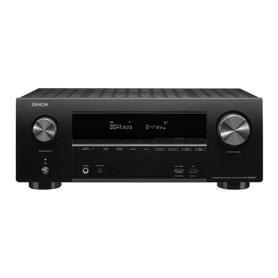
Denon AVR-X2600H Integrated Network AV Receiver Quick Start Guide
Brand:
Denon
| Category:
Stereo Receiver
| Size: 0.66 MB
Table of Contents
Welcome
Before You Begin
Required for Setup
Optional
What's In the Box
Important: External Antennas
Setup
Installing batteries in the remote control unit
Connecting the receiver
Following the On-Screen Setup Assistant
Downloading the Mobile Apps
Documents / Resources
References
Advertisement
Denon AVR-X2600H Series Service Manual (175 pages)
Integrated Network Av receiver
Brand:
Denon
| Category:
Stereo Receiver
| Size: 20.6 MB
Table of Contents
Before Servicing this Unit
2
Safety Precautions
3
Leakage Current Check
3
Concerning Important Safety Parts
3
Note for Schematic Diagram
4
Handling the Semiconductor and Optics
4
Ground for Human Body
4
Ground for Workbench
4
Online Parts List
5
Accessing the Parts List
5
Searching Part Numbers or Ref. Numbers
5
Note for Parts List
5
Serial Number
6
Serial Number Organization
6
SKU Code of this Unit
6
Post-Service Precautions
7
Initializing this Unit AVR-X2600H
7
Initializing this Unit AVR-S950H
7
Jig for Servicing
7
Electrical
8
Schematic Diagrams
8
Printed Circuit Boards
8
Schematic Diagrams
9
SCH01 TMDS261B, Earc
9
Sch02 Hdmi Sw1
10
Sch03 Hdmi Sw2
11
Sch04 Adv8003
12
Sch05 Adv8003 Ddr
13
Sch06 Hdmi Tx
14
Sch07 Net Phy
15
Sch08 Cpu
16
Sch09 Cpu Level Chg
17
Sch10 Dsp
18
Sch11 dir A.pld
19
Sch12 Main Dac
20
Sch13 D.supply
21
Sch14 Digital Cnt
22
Sch15 Input 1
23
Sch16 Input 2
24
Sch17 Video
25
Video Part
25
Sch18 Front Cnt
26
Sch19 Rc-5
27
Sch20 Amp1
28
Sch21 Amp2
29
Sch22 Spk
30
Sch23 Tuner Reg
31
Sch24 Rs Cnt, Audio in
32
Sch25 Front
33
Sch26 Smps
34
Sch27 F-Hdmi
35
Printed Circuit Boards
36
Digital, F Hdmi
36
Lead-Free Solder
36
Input, Video, Front Cnt
37
Amp
38
Main, Audio In, Rs Cnt, Guide L, Top_Guide
39
Front, Cnt, Rs232, Function, Usb
40
Smps
41
Level Diagram
42
FRONT Ch
42
CENTER, SURROUND, SURR.BCK Ch
43
SUBWOOFER Ch
44
ZONE2 Ch (W/ Source)
45
ZONE2 Ch (W/O Source)
46
Block Diagram
47
Analog Audio Diagram
47
Avr_S950H / X2600H / Analog Audio Diagram
47
Digital Audio Diagram
48
Avr_S950H / X2600H Digital Audio Diagram
48
Video Diagram
49
Avr_S950H / X2600H Video Diagram
49
Power Diagram
50
Avr_S950H / X2600H Wire Diagram
51
Wiring Diagram
51
Semiconductors
52
IC's
52
Cs49844A (Digital : U1073)
56
W9812G6Kh-5 (Digital : U1023)
56
Pin Description
56
Ak4458Vn (Digital : U1051)
57
Pin Function
57
Functional Block Diagram
58
Pcm5100A (Digital : U1052, U1054)
59
Nju72343 (Input : U4202)
59
Nju72750A (Input : U4201,U4203)
59
Device Information
59
Wide Band 3-Input 1-Output 3-Circuit Video Amplifier
60
Package Outline
60
Fl Display
61
Pin Connection
61
Remote Code Table
62
Format Sharp
62
Format Kaseikyo
63
DATA CONSTRUCTION 48Bits
63
REMOTE ID SETTING: (Default ID 1)
63
Main Zone
64
Zone2
65
Analog Tuner/Dab
66
Heos Music
66
Mechanical
67
Disassembly
68
Front Panel Assy
69
Explanatory Photos for DISASSEMBLY
69
The Viewpoint of each Photograph
69
Top Cover
69
Radiator Assy
70
Digital Pcb
70
Video Pcb
71
Main Pcb
71
Smps Pcb
71
Trans
71
Exploded View
72
Packaging View
73
Repair Information
74
Troubleshooting
74
Diagnostic Mode
74
Trouble Shooting
75
Power
75
The Unit Does Not Power on
75
Fuse Is Blown
75
Analog Video
76
DIGITAL Test Point
76
VIDEO Test Point
76
Hdmi/DVI
78
No Picture or Sound Is Output (HDMI to HDMI)
78
Audio Check
80
No Audio Output
80
Power AMP (AMP PCB)
81
Analog Audio
81
Network / Bluetooth / USB
82
Cannot Connect to the Network
82
Cannot Establish a Bluetooth Connection
83
Cannot Recognize the Connected USB Device
84
No Picture or Sound Is Output
84
USB Test Point
85
Operation Waveform for each Part
86
HDMI "Rx/Tx" Failure Detection
87
Prior Checking
87
Preparations for Checking HDMI Switcher Reception
88
Necessary Device
88
Device Connection Method
88
Device Configuration Method
88
Indicator Lights
89
Starting Detecting the Point of Failure
90
Start in HDMI Diagnostics Mode
90
Display When an Error Is Not Detected
90
Error Code Table
90
Contact Support
90
Error Code H1-01 Failure Detection Procedure
92
Error Code H1-02 Failure Detection Procedure
94
Error Code H1-03 Failure Detection Procedure
96
Error Code H1-06 Failure Detection Procedure
98
Error Code H1-14 Failure Detection Procedure
100
Error Code H1-15 Failure Detection Procedure
100
Error Code H1-04 Failure Detection Procedure
101
Error Code H1-08 Failure Detection Procedure
102
Error Code H1-12 Failure Detection Procedure
104
Error Code H1-16 Failure Detection Procedure
106
HDMI Rx [MN864788] Failure Detection Procedure
108
HDMI DDC Buffer IC [AD8195] Failure Detection Procedure
111
HDMI Transmission IC [MN864788] Failure Detection Procedure
114
GUI IC [ADV8003] Failure Detection Procedure
122
HDMI SW IC [TMDS261B] Failure Detection Procedure
123
Device Implementation Location
124
Clock Flow & Wave Form in Digital Block
125
Wave Form
125
Special Mode
126
Special Mode Setting Button AVR-X2600H
126
Special Mode Setting Button AVR-S950H
127
Version Display Mode
128
Starting up
128
Display Order
128
Error Display
129
Version Display in the Setup Menu
130
PANEL / REMOTE LOCK Selection Mode
131
Displaying and Selecting each Mode
131
Selecting the Mode for Service-Related
132
Service Check
132
Protection History Display Mode
133
232C Standby Clear Mode (AVR-X2600H E3 Only)
134
Clearing the Protection History
134
Warning Displays by POWER LED
134
Operation Info Mode
135
TUNER STEP Mode (E3 / E2 Only, Except DABE2)
136
Remote ID Setup Mode
136
Protection Pass Mode
137
Network Initialization Mode
137
Clearing the Operation Info
138
Log Capture Feature
138
Diagnostic Mode
139
Service Path Check Mode
139
Canceling Diagnostic Mode
139
Selecting Items to Check
139
Confirmation Items for the Video System
141
Diagnostic Path Diagram
142
Headphone out
144
Front Hdmi
154
Input Select
154
Jig for Servicing
162
Adjusting Idling Current
164
Adjustment Procedure
164
Updating
165
Procedure after Replacing the Pcb.
166
Procedure after Replacing the U-Com, Etc.
166
Firmware Update Procedure
167
Items Necessary for Update
167
Update Preparation with a USB Flash Drive
168
Connecting to the USB Flash Drive
168
Unzipping the Downloaded File
168
Update Method When the DIGITAL PCB or Network Module Is Replaced
169
File Structure on USB Flash Drive
169
Start the Update
169
Update Method for Service Region Settings
170
Creating a Service Region Settings File
170
Starting Service Region Settings
170
Normal Firmware Update Method from USB Flash Drive
171
Start Normal Update
171
Normal Firmware Update Method from OTA
172
Network Connection
172
Check and Update the Firmware
172
About the Error Codes
173
Remedies
173
Device ID Table
173
Denon AVR-X2600H Series Owner's Manual (291 pages)
INTEGRATED NETWORK AV RECEIVER
Brand:
Denon
| Category:
Stereo Receiver
| Size: 14.18 MB
Advertisement
Denon AVR-X2600H Series Quick Start Manual (14 pages)
INTEGRATED NETWORK AV RECEIVER
Brand:
Denon
| Category:
Stereo Receiver
| Size: 1.06 MB
Table of Contents
Before You Begin
2
Required for Setup
2
Installing Batteries in the Remote Control Unit
5
Connecting the Receiver
6
Advertisement
Related Products
Denon AVR-X2500H
Denon AVR-X2700H
Denon AVRX2600HBKE3
Denon AVRX2600HBKE2
Denon AVRX2600HDABBKE2
Denon AVRX2600HBKE1C
Denon AVRX2600HK
Denon AVR-X2800H
Denon AVR-X2600H DAB
Denon AVR-X6700H
Denon Categories
Stereo Receiver
Receiver
CD Player
Amplifier
DVD Player
More Denon Manuals
Login
Sign In
OR
Sign in with Facebook
Sign in with Google
Upload manual
Upload from disk
Upload from URL