Sign In
Upload
Manuals
Brands
Delta Tau Manuals
DC Drives
Geo MACRO
Delta Tau Geo MACRO Manuals
Manuals and User Guides for Delta Tau Geo MACRO. We have
1
Delta Tau Geo MACRO manual available for free PDF download: User Manual And Reference Manual
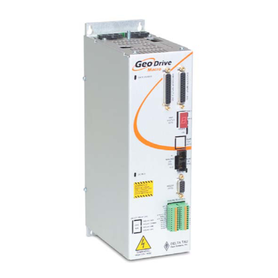
Delta Tau Geo MACRO User Manual And Reference Manual (205 pages)
Direct PWM Amplifier over MACRO
Brand:
Delta Tau
| Category:
DC Drives
| Size: 3.34 MB
Table of Contents
Operating Conditions
3
Safety Instructions
3
Table of Contents
7
Introduction
13
User Interface
13
Geo MACRO Drives
13
Geo PMAC Drives
14
Geo Direct-PWM Drives
14
MACRO Defined
14
Feedback Devices
15
Compatible Motors
15
Maximum Speed
15
Torque
15
Motor Poles
16
Motor Inductance
16
Motor Resistance
16
Motor Back EMF
16
Motor Torque Constant
17
Motor Inertia
17
Motor Cabling
17
Specifications
19
Part Number
19
Geo MACRO Feedback Options
20
Package Types
20
Electrical Specifications
21
230VAC Input Drives
21
480VAC Input Drives
23
Environmental Specifications
25
Recommended Fusing and Wire Gauge
25
Receiving and Unpacking
27
Use of Equipment
27
Mounting
29
Low Profile
30
Single Width
31
Double Width
32
Connections
33
System (Power) Wiring
33
Wiring AC Input, J1
35
Wiring Earth-Ground
35
Wiring 24 V Logic Control, J4
36
Wiring the Motors
36
J2: Motor 1 Output Connector Pinout
36
J3: Motor 2 Output Connector Pinout
36
Wiring the Motor Thermostats
37
Wiring the Regen (Shunt) Resistor, J5
37
J5: External Shunt Connector Pinout
38
Shunt Regulation
39
Minimum Resistance Value
39
Maximum Resistance Value
39
Energy Transfer Equations
39
Bonding
41
Filtering
42
CE Filtering
42
Input Power Filtering
43
Motor Line Filtering
43
I/O Filtering
43
Connecting Main Feedback Sensors (X1 & X2)
44
Digital Quadrature Encoders
44
Digital Hall Commutation Sensors
45
SSI Encoders
45
Sinusoidal Encoders
46
Hiperface® Interface
47
Endat Interface
48
Resolvers
49
Connecting Secondary Quad. Encoders (X8 & X9)
50
Connecting General Purpose I/O & Flags (X3)
51
Sample Wiring the I/O
51
Sample Wiring the Flags
52
Connecting MACRO Ring
53
Fiber Optic MACRO Connections (X5)
53
Copper MACRO Connections (X10 &X11)
53
Connecting Optional Analog Inputs (X6 & X7)
54
Software Setup for Geo Macro Drives
55
Introduction
55
Establishing MACRO Communications with Turbo PMAC
55
MACRO Ring Frequency Control Variables
55
I7: Phase Cycle Extension
55
I6840: MACRO IC 0 Master Configuration
56
I6890/I6940/I6990: MACRO IC 1/2/3 Master Configuration
56
I6841/I6891/I6941/I6991: MACRO IC 0/1/2/3 Node Activation Control
56
I70/I72/I74/I76: MACRO IC 0/1/2/3 Node Auxiliary Function Enable
57
I71/I73/I75/I77: MACRO IC 0/1/2/3 Node Protocol Type Control
58
I78: MACRO Master/Slave Auxiliary Communications Timeout
58
I79: MACRO Master/Master Auxiliary Communications Timeout
58
I80, I81, I82: MACRO Ring Check Period and Limits
58
MACRO Node Addresses
59
Using the Turbo PMAC Setup Program
63
Using the PEWIN32PRO 2 MACRO Ring ASCII Feature
70
PEWIN32PRO Suite 2 MACRO Status Window
74
Ring Order Communications Method
75
MACRO ASCII Communications
76
How to Enable and Disable MACRO ASCII Communication Mode
76
Setting up Primary Feedback
79
Device Selection Control
79
Setting up Digital Quadrature Encoders
79
Setting up SSI Encoders
79
Setting up Sinusoidal Encoders
81
Principle of PMAC Interpolation Operation
81
Setting up Endat
84
Setting up Resolvers
84
Setting up the Phase Shift (MI941) Manually
85
Setting up the Resolver for Power-On Absolute Position
85
Scaling the Feedback Units
86
Setting up Secondary Encoders
87
Setting up the Turbo Pmac Conversion Table
89
Setting up Turbo Motor Operation
91
Turbo PMAC Basic Setup for Brushless Servo or Induction Motor
91
Turbo PMAC Basic Setup for DC Brush Motors
92
Instructions for Direct-PWM Control of Brush Motors
97
PWM/ADC Phase Match
97
Synchronous Motor Stepper Action
97
Current Loop Polarity Check
97
Troubleshooting
98
Testing PWM and Current Feedback Operation
98
Purpose
98
Preparation
99
Position Feedback and Polarity Test
99
Setting up Hall Commutation Sensors
100
Signal Format
100
Using Hall Effect Sensors for Phase Reference
101
Determining the Commutation Phase Angle
101
Finding the Hall Effect Transition Points
101
Calculating the Hall Effect Zero Point (HEZ)
102
Determining the Polarity of the Hall Effects - Standard or Reversed
104
Software Settings for Hall Effect Phasing
104
Setting I 2 T Protection
108
Calculating Minimum PWM Frequency
109
Geo MACRO Drive User and Reference Manual
91
Setting up Discrete Inputs and Outputs
111
Inputs and Outputs
111
Ring Break Output Indicator Ms{Node},Mi13
112
Setting up the Analog Inputs (X6 and X7)
112
Limit and Flag Circuit Wiring
114
Connecting Limits/Flags to the Geo Drive
114
Setting up Position Compare (EQU) Outputs
115
Setting up for a Single Pulse Output
115
Setting up for Multiple Pulse Outputs
116
Connectors
117
Connector Pinouts
117
X1: Encoder Input 1
117
X2: Encoder Input 2
118
X3: General Purpose I/O
119
X4: Safety Relay (Optional)
120
X6: Analog in 1 (Optional 3/4/5)
120
X7: Analog in 2 (Optional 3/4/5)
120
X8: S. Encoder 1
121
X9: S. Encoder 2
121
X13: Discrete I/O
121
J1: AC Input Connector Pinout
122
J2: Motor 1 Output Connector Pinout
122
J3: Motor 2 Output Connector Pinout (Optional)
122
J4: 24VDC Input Logic Supply Connector
122
J5: External Shunt Connector Pinout
122
MACRO Link Connectors
123
X5: MACRO I/O, MACRO Fiber Optic Transceiver (Optional)
123
X10 and X11 MACRO RJ-45 Copper Connectors
123
USB Connector
123
X12: USB Universal Serial Bus Port
124
Troubleshooting
125
Error Codes
125
D1: Geo MACRO Drive Status Display Codes
125
MACRO Network Errors
126
Status Leds
127
Geo MACRO Drive Ring Status Error Codes
128
Ms{Node},Mi4 Geo MACRO Status Word (Read Only)
128
Ms{Node},Mi6 Status Word Control
129
Status Word
129
Turbo Pmac2 Related I-Variable Reference
131
Ixx10: Motor XX Power-On Servo Position Address
131
Ixx25, Ixx24: Flag Address and Mode
133
Ixx70, Ixx71: Commutation Cycle Size
135
Ixx72: Commutation Phase Angle
135
Ixx75: Absolute Phase Position Offset
135
Ixx81: Motor XX Power-On Phase Position Address and Mode
136
Ixx82: Current Loop Feedback Address
137
Ixx83: Commutation Feedback Address
138
Ixx91: Motor XX Power-On Phase Position Format
138
Ixx95: Motor XX Power-On Servo Position Format
141
Ixx97 Motor XX Position Capture and Trigger Mode
143
Geo Macro Drive MI-Variable Reference
145
Global MI-Variables
145
Ms{Node},Mi0 Geo MACRO Drive Firmware Version (Read Only)
145
Ms{Node},Mi1
145
Geo MACRO Drive Firmware Date (Read Only)
145
Ms{Node},Mi2 and MI3
145
(Reserved for Future Use)
145
Ms{Node},Mi4
146
Geo MACRO Drive Status Word (Read Only)
146
Ms{Node},Mi5
146
Ring Error Counter
146
Ms{Node},Mi6
147
Status Word Control
147
Ms{Node},Mi7
147
Geo MACRO Error Counter
147
Ms{Node},Mi8
147
Geo MACRO Ring Check Period
147
Ms{Node},Mi9
147
Geo MACRO Ring Error Shutdown Count
147
Ms{Node},Mi10 Geo MACRO Sync Packet Shutdown Count
148
Ms{Node},Mi11 Station Order Number
148
Ms{Node},Mi12 Card Identification (Read Only)
149
Ms{Node},Mi13 Ring Break Output Indicator
149
Ms{Node},Mi100
150
Motor Activation Control Word
150
Ms{Node},Mi101-102
150
Primary Feedback Selection
150
Ms{Node},Mi103 sin Encoder/ Resolver #1 Bias
151
Ms{Node},Mi104 sin Encoder/ Resolver #2 Bias
151
Ms{Node},Mi105 Cosine Encoder/ Resolver #1 Bias
151
Ms{Node},Mi106 Cosine Encoder/ Resolver #2 Bias
151
Ms{Node},Mi107 Motor 1 Encoder-Loss Mask
152
Ms{Node},Mi108 Motor 2 Encoder-Loss Mask
152
Primary Channel Node-Specific Gate Array MI-Variables
154
Ms{Node},Mi910 Primary Encoder/Timer N Decode Control
154
Ms{Node},Mi911 Primary Enc. Position Compare N Channel Select
155
Ms{Node},Mi912 Primary Encoder N Capture Control
155
Ms{Node},Mi913 Primary Encoder Capture N Flag Select Control
156
Ms{Node},Mi914 Primary Encoder N Gated Index Select
156
Ms{Node},Mi915 Primary Encoder Index Gate State/Demux Control
157
Ms{Node},Mi910 Secondary Encoder Decode Control
158
Ms{Node},Mi911 Secondary Encoder Counter Direction
158
Ms{Node},Mi912 Secondary Encoder Index Capture Control
159
Ms{Node},Mi913 Secondary Encoder Home Flag Capture Control
159
Ms{Node},Mi914 Secondary Encoder Filter Control
159
Ms{Node},Mi915 Secondary Encoder Capture Flag Select Control
160
Ms{Node},Mi916 Output N Mode Select
160
Ms{Node},Mi917 Output N Invert Control
160
Ms{Node},Mi918 Output N PFM Direction Signal Invert Control
161
Ms{Node},Mi919 Hardware 1/T
161
Ms{Node},Mi921 Flag Capture Position (Read Only)
162
Ms{Node},Mi922 ADC a Input Value (Read Only)
162
Ms{Node},Mi923 Compare Auto-Increment Value
162
Ms{Node},Mi924 ADC B Input Value (Read Only)
162
Ms{Node},Mi925 Compare a Position Value
163
Ms{Node},Mi926 Compare B Position Value
163
Ms{Node},Mi927 (Reserved for Future Use)
163
Ms{Node},Mi928 Compare-State Write Enable
163
Ms{Node},Mi929 Compare-Output Initial State
163
Geo MACRO Drive User and Reference Manual
160
General Hardware Setup MI-Variables
164
Ms{Anynode}, MI930 SSI Channel 1 Control Word
164
Ms{Anynode}, MI931 SSI Channel 2 Control Word
164
Ms{Anynode}, MI932
165
Resolver Excitation Frequency Divider
165
Ms{Anynode}, MI933
165
SSI Clock Frequency Divider
165
Ms{Anynode},Mi934-MI939
165
(Reserved for Future Use)
165
Ms{Anynode}, MI940
165
Resolver Excitation Gain
165
Ms{Anynode}, MI941
166
Resolver Excitation Phase Offset
166
Ms{Anynode},Mi942
166
ADC Strobe Word Channel 1* & 2
166
Ms{Node},Mi943 Encoder Power Control Bit
166
Ms{Node},Mi944-MI949 (Reserved for Future Use)
166
Global & 2-Axis Board I-Variables
167
Ms{Node},Mi992 Maxphase Frequency Control
167
Ms{Node},Mi993 Hardware Clock Control Handwheel Channels
167
Ms{Node},Mi994 PWM Deadtime
169
Ms{Node},Mi995 MACRO Ring Configuration/Status
169
Ms{Node},Mi996 MACRO Node Activate Control
170
Ms{Node},Mi997 Phase Clock Frequency Control
172
Ms{Node},Mi998 Servo Clock Frequency Control
172
Absolute Power on Online Commands
173
Fiber Optic Cable Ordering Information
178
Mating Connector and Cable Kits
178
Appendix A
178
Connector and Pins Part Numbers
180
Cable Drawings
182
Regenerative Resistor: GAR78/48
188
Type of Cable for Encoder Wiring
189
Schematics
192
X3: Discrete I/O
192
Appendix B
192
X6 and X7: Analog Inputs
194
X8 and X9 Secondary Encoders (3 and 4)
195
Communication to the Geo MACRO Via the USB Port
196
Appendix C
196
MACRO Flag Transfer Location
198
Appendix D
198
Turbo PMAC2 Node Addresses
199
ADC Register Table
201
Stepping through an Electrical Cycle
202
Manually Stepping through an Electrical Cycle at 30 Degree Increments
202
Example 1 of Hall Effect Values
203
Example 2 of Hall Effect Values
204
Useful Notes
205
Advertisement
Advertisement
Related Products
Delta Tau Geo Direct PWM Amplifier
Delta Tau Geo Brick
Delta Tau Geo Direct PWM Amplifie
Delta Tau Categories
Computer Hardware
Controller
Amplifier
Power Supply
PCI Card
More Delta Tau Manuals
Login
Sign In
OR
Sign in with Facebook
Sign in with Google
Upload manual
Upload from disk
Upload from URL