Sign In
Upload
Manuals
Brands
Danfoss Manuals
Inverter Drive
VLT 2015
User Manuals: Danfoss VLT 2015 Frequency Inverter Drive
Manuals and User Guides for Danfoss VLT 2015 Frequency Inverter Drive. We have
1
Danfoss VLT 2015 Frequency Inverter Drive manual available for free PDF download: Manual
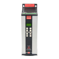
Danfoss VLT 2015 Manual (111 pages)
Brand:
Danfoss
| Category:
Inverter Drive
| Size: 1.57 MB
Table of Contents
Contents
1
These Rules Concern Your Safety
4
Warning against Improper Start
4
Table of Contents
5
Before You Start
6
Mechanical Installation
6
Electrical Installation
6
Control Cables
8
EMC Correct Installation
9
General
9
How to Install
9
Cable for Serial Communication
9
Instructions for Installation
9
Three-Phase Mains Connection
10
Single-Phase Mains Connection
10
Between PC and VLT Frequency Converter
10
For Further Information
11
Installation Guide
12
Technical Data
12
Mains Supply Connection
12
Motor Cable Connection
12
After Installation
13
Quick Setup
14
A Simple Connection Example
14
If You Are Familiar with a VLT
14
If You Are Not Familiar with a VLT
14
Quick Set
14
How to Program
15
Description of Connection Terminals
16
Survey of Terminals
16
Check Grounding
17
How to Check Connection of Control Cables
17
Prefuses
17
Basic Settings
18
Commissioning and Testing
18
How the VLT Works
21
How the VLT Is Built up
22
Improved Process
22
Improved Quality
22
Saved Energy
22
The Danfoss VVC Principle
23
Constant Torque CT
24
Factory-Programmed Optimization
24
Start Compensation
24
Start Voltage
24
Advanced Motor Protection
25
Control Accuracy
25
Galvanic Isolation
25
Programmable Control Inputs and Signal Outputs in 2 Setups
25
Functional Diagram VLT 2010-2030 Single-Phase/Three-Phase 208-240 V
26
Function Diagram VLT 2040-2050, 3-Phase 208-240 V
27
Functional Diagram VLT 2020-2060 Three-Phase 380-460 V
28
How to Size Your VLT
29
Selection of Frequency Converter
30
Sizing When You Know the Motor Current
30
Which One to Choose?
31
How to Find the Right Code Number
32
Product Range
32
Accessories/Options to the VLT Series 2000
33
Brake Function
33
LC and RFI Filter (Module)
34
Motor Coils (Module)
34
RFI and Motor Filter (Module)
34
Dimensions
35
Technical Data
38
VLT 2000 Series Built-In Compact RFI Filter
33
VLT 2000 Series Built-In RFI Filter en 55011 1A
33
How to Install Your VLT
41
How to Connect the VLT to the Motor
42
Survey of Connection Terminals
42
How to Connect Control Signals
43
Extra Protection
44
High Voltage Test
44
Side by Side Mounting
44
What Cables to Use
44
How to Operate Your VLT
45
Operating Your VLT
46
The Display
46
The Push Buttons
46
Altering a Data Value (Digits)
47
Altering a Data Value (Text)
47
Back to Display Group
48
Back to the Factory Setting
48
How to Lock Programming Function
48
Operating Without Control Panel
48
The Groups (Modes)
48
The Different Groups (Modes)
49
The Light Diodes
48
The Control Possibilities of the VLT
51
Control with Open Loop
52
Load and Motor (Group 1)
52
Operation and Display (Group 0..)
52
Control with Closed Loop
53
Serial Data Interface (Group 5..)
54
VLT Status
56
VLT Control Commands
57
000 Language Select (LANGUAGE)
61
001 Menu Setup Select (MENU SETUP)
61
002 Setup Copy (MENU SET COPY)
61
Description of Parameters
61
004 Local Reference (LOCAL SPEED)
62
005 Display Value (VALUE at MAX.)
62
006 Local Reset (LOCAL RESET)
62
007 Local Start / Stop (LOC START/STOP)
62
101 Speed Control (SPEED CONTROL)
63
102 Current Limit Control (CURRENT LIMIT)
63
103 Motor Power (MOTOR POWER)
63
104 Motor Voltage (MOTOR VOLTAGE)
63
105 Motor Frequency (MOTOR FREQ)
64
107 Motor Current (MOTOR CURRENT)
64
108 Motor Magnetising Current (MOTOR MAG.AMP)
64
109 Start Voltage (START VOLTAGE)
64
110 Start Compensation (START COMP.)
65
111 U/F Ratio (V/F. RATIO)
65
112 Slip Compensation (SLIP COMP)
65
114 Feedback Type (FEEDBACK TYPE)
65
119 FF Factor (FEED FWD FACTR)
66
120 Controller Range (CONTRL RANGE)
66
121 Proportional Gain (PROPRT /L GAIN)
66
122 Integral Time (INTEGRAL TIME)
66
200 Frequency Range (FREQ RANGE)
67
201 Min. Frequency (MIN FREQUENCY)
67
202 Max. Frequency (MAX FREQUENCY)
67
203 Jog Frequency (JOG FREQUENCY)
67
204 Digital Reference Type (DIG. REF. TYPE)
68
209 Current Limit (CURRENT LIMIT)
68
210 Warning: Frequency Low (LOW FREQ WARN)
69
211 Warning: Frequency High (HI FREQ WARN)
69
213 Warning: Current High (HI CURR WARN)
69
215 Ramp-Up Time 1 (RAMP up TIME)
69
224 Carrier Frequency (CARRIER FREQ.)
70
230 Digital Speed Up/Down (SPEED up DOWN)
70
300 Brake Function (BRAKE OPTION)
70
306 DC Braking Time (DC-BRAKE TIME)
70
308 DC Brake Voltage (DC-BRK VOLTAGE)
71
309 Reset Mode (RESET MODE)
71
310 Trip Delay at Current Limit (TRIP DLY@C.LIM)
71
315 Motor Thermal Protection (MOTOR THERMAL)
71
402 Terminal 18 Start (INPUT 18)
72
Digital Reference Select
72
Pulse Start
72
Speed up
72
403 Terminal 19 Reversing (INPUT 19)
73
404 Terminal 27 Stop (INPUT 27)
73
405 Terminal 29 Jog (INPUT 29)
74
408 Terminal 46 Output (LOG.OUTPUT 46)
75
409 Terminal 01
76
411 Analogue Input Current (ANALOG REFTYPE)
76
412 Terminal 53
76
413 Terminal 60
76
500 Address (ADDRESS)
77
501 Bit/Sec. Baud Rate (BAUD RATE)
77
502 Data Readout (DATA READOUT)
77
503 Coasting (COAST)
78
504 Q Stop (Q-STOP)
78
505 DC Brake (DC-BRAKE)
79
506 Start (Start)
79
507 Direction (DIRECTION)
79
511 Bus Jog 1 (BUS JOG 1)
79
Display Messages
81
Alarm Messages
82
Enab Stop
82
Status Messages
82
Unit Ready
82
Reset Messages
83
Warning Messages
83
Special Conditions
85
The EMC Directive (89/336/EEC)
86
The Low-Voltage Directive (73/23/EEC)
86
The Machine Directive (89/392/EEC)
86
What Is CE Labelling?
86
Earthing
88
High Frequency Earthing
88
Safety Earthing
88
Radio Interference in General
89
EMC Test Results
90
Emission
90
Immunity
91
Acoustic Noise
92
Extreme Running Conditions
92
Motor Noise
92
Short Circuit
92
Air Humidity
93
Efficiency
93
Efficiency of the VLT 2000 Series
93
Motor Efficiency
93
Derating for High Ambient Temperature
94
Du/Dt Measurements
94
Derating for Air Pressure
95
Derating for Higher Switching Frequency than 4.5 Khz
95
Derating for Running at Low Speed
95
Typical Motor Derating
95
Cut-In Current
96
Maximum Cut-In Current Surge Measured at 25°C
96
Motor Does Not Run
98
Motor Runs Unevenly
98
Service
98
Troubleshooting
98
No Message or Light in Display
99
Your Parameter Settings
102
Advertisement
Advertisement
Related Products
Danfoss VLT 2000 Series
Danfoss VLT 2040
Danfoss VLT 2060
Danfoss VLT 2025
Danfoss VLT 5001
Danfoss VLT 5006
Danfoss VLT 5008
Danfoss VLT 5022
Danfoss VLT 5042
Danfoss VLT 5402
Danfoss Categories
Controller
DC Drives
Thermostat
Control Unit
Air Compressor
More Danfoss Manuals
Login
Sign In
OR
Sign in with Facebook
Sign in with Google
Upload manual
Upload from disk
Upload from URL