Sign In
Upload
Manuals
Brands
Daikin Manuals
Air Conditioner
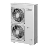
Super Multi Plus E-Series FTXS35G2V1B
Daikin Super Multi Plus E-Series FTXS35G2V1B Manuals
Manuals and User Guides for Daikin Super Multi Plus E-Series FTXS35G2V1B. We have
1
Daikin Super Multi Plus E-Series FTXS35G2V1B manual available for free PDF download: Service Manual
Daikin Super Multi Plus E-Series FTXS35G2V1B Service Manual (492 pages)
Brand:
Daikin
| Category:
Air Conditioner
| Size: 25.78 MB
Table of Contents
Table of Contents
3
Part 1 List of Functions
3
Part 2 Specifications
3
Part 3 Printed Circuit Board Connector Wiring Diagram
3
Part 4 Refrigerant Circuit
3
Part 5 Function
3
Introduction
8
Safety Cautions
8
Used Icons
12
Part 1 List of Functions
13
Functions
14
Part 2 Specifications
22
Part 2 Specifications
23
Specifications
23
Outdoor Unit
23
BP Unit
24
Indoor Unit
25
Duct Connected Type
33
Ceiling Mounted Cassette Type
34
Ceiling Suspended Type
37
Part 3 Printed Circuit Board Connector Wiring Diagram
38
Outdoor Unit
39
Rmxs112/140/160E8V1B
39
BP Unit
42
Bpmks967B2B/B3B
42
Indoor Unit
43
Wall Mounted Type
43
Floor Standing Type
56
Floor / Ceiling Suspended Dual Type
58
Duct Connected Type
60
Ceiling Mounted Cassette Type
62
Ceiling Mounted Built-In Type
66
Ceiling Suspended Type
71
Remote Controller
73
Wired Remote Controller
73
Wireless Remote Controller
75
Part 4 Refrigerant Circuit
77
Refrigerant Circuit
78
Outdoor Unit
78
Refrigerant Circuit Part
78
BP Unit
80
Functional Parts Layout
81
Outdoor Unit
81
Refrigerant Flow for each Operation Mode
83
Cooling Operation
83
Heating Operation
84
Cooling Oil Return Operation
85
Heating Oil Return Operation & Defrost Operation
86
Part 5 Function
87
Operation Mode
89
Basic Control
90
Normal Operation
90
Compressor PI Control
91
Electronic Expansion Valve PI Control
92
Cooling Operation Fan Control
93
Special Control
94
Startup Control
94
Oil Return Operation
95
Defrosting Operation
97
Pump-Down Residual Operation
98
Restart Standby
99
Stopping Operation
99
Protection Control
100
High Pressure Protection Control
100
Low Pressure Protection Control
101
Discharge Pipe Temperature Protection Control
102
Inverter Protection Control
103
Freeze-Up Protection Control
104
Dew Condensation Prevention Control
105
Other Control
106
Demand Control
106
Heating Operation Prohibition Control
106
BP Unit Control
107
BP Unit Command Conversion
107
BP Unit Electronic Expansion Valve Control
108
SH Control in Cooling Operation
110
SC Control in Heating Operation
111
Heat Exchanger Isothermal Control in Heating Operation
111
Indoor Unit Control (RA Models)
112
Temperature Control
112
Operation Starting Control
113
Airflow Direction Control
114
Fan Speed Control for Indoor Units
116
Program Dry Operation
117
Automatic Operation
118
Thermostat Control
119
NIGHT SET Mode
121
ECONO Operation
122
HOME LEAVE Operation
123
2-Area INTELLIGENT EYE Operation
124
INTELLIGENT EYE Operation
126
Inverter POWERFUL Operation
127
Other Functions
129
Weekly Timer Operation
130
Indoor Unit Control (SA Models)
131
Drain Pump Control
131
Thermostat Sensor in Remote Controller
133
Freeze Prevention Control
135
Hot Start Control (in Heating Operation Only)
136
Part 6 Test Operation and Field Settings
137
Test Operation
138
Procedure and Outline
138
Check Operation
139
Operation When Power Is Turned on
140
Outdoor Unit PCB Layout
141
BP Unit
142
RA Indoor Unit - F(C)TXG, FTXS, FVXS, FLXS, FDXS Series
144
SA Indoor Unit - FFQ, FCQ, FDBQ, FBQ, FHQ Series
146
Check Points
146
Field Settings
148
Outdoor Unit
148
RA Indoor Unit - F(C)TXG, FTXS, FVXS, FLXS, FDXS Series
166
Model Type Setting
166
When 2 Units Are Installed in 1 Room
166
Jumper and Switch Settings
169
SA Indoor Unit - FFQ, FCQ, FDBQ, FBQ, FHQ Series
170
Part 7 Operation Manual
178
System Configuration
179
Outdoor Unit
180
RMXS Series
180
FTXG-J, CTXG-J Series - ARC466A1
181
Name of Parts
181
Signal Transmitter
183
Temperature Adjustment Buttons
183
Mode Selector Button
184
Off Timer Button
184
Fan Operation
185
Operating Conditions
186
Operation Manual
186
Adjusting the Airflow Direction and Rate
187
Comfort Airflow Operation
189
Powerful Operation
192
Outdoor Unit Quiet Operation
193
Off Timer Operation
195
On Timer Operation
196
Note for Multi System
203
FTXS-G, FVXS Series - ARC452A1, A3
204
Names of Parts
208
Names of Parts
210
Opening the Front Panel
211
To Change the Airflow Rate Setting
215
Adjusting the Airflow Direction
216
Comfort Airflow and Intelligent Eye Operation
222
Timer Operation
231
Arc433B41, B67, B69, B70
239
FTXG-E, CTXG-E, FTXS-F, FLXS, FDXS Series
239
To Change the Air Flow Rate Setting
245
Adjusting the Air Flow Direction
246
To Use on Timer Operation
261
RA Indoor Unit
181
SA Indoor Unit - FFQ, FCQ, FDBQ, FBQ, FHQ Series
263
Brc1D528
263
Brc1E51A7
278
Names and Functions
280
Automatic Operation Mode
281
Basic Operation Method
283
Remote Controller Functions
283
Program Dry
288
Key Lock
292
Airflow Direction
299
Ventilation Mode
303
Timer Settings
303
Schedule Timer
305
Holiday Setting
309
Convenient Functions
314
Contrast Adjustment
314
Clock Setting
317
Setting the Clock
317
Useful Information
322
Brc7E530W, Brc7F532F, Brc7Ea63W
323
Operation Range
326
Operation Procedure
327
Part 8 Troubleshooting
335
Troubleshooting with LED
337
Outdoor Unit
337
BP Unit
342
Indoor Unit
343
Operation Lamp
343
Service Check Function
346
RA Indoor Unit - F(C)TXG, FTXS, FVXS, FLXS, FDXS Series
346
SA Indoor Unit - FFQ, FCQ, FDBQ, FBQ, FHQ Series
355
Error Codes and Description
362
Troubleshooting for RA Indoor Unit
364
Indoor Unit PCB Abnormality
364
Freeze-Up Protection Control or Heating Peak-Cut Control
365
Fan Motor or Related Abnormality
367
Thermistor or Related Abnormality (Indoor Unit)
370
Front Panel Open / Close Fault
371
Fan Motor Connector Output Check
372
Check for RA Indoor Unit
372
Thermistor Resistance Check
373
Hall IC Check
374
Troubleshooting for SA Indoor Unit
375
Indoor Unit PCB Abnormality
375
Drain Water Level System Abnormality
376
Fan Motor or Related Abnormality (FHQ Series)
378
Swing Motor Lock (FHQ Series)
379
Drain System Abnormality
380
Indoor Liquid Pipe Thermistor (R2T) Abnormality
381
Indoor Heat Exchanger Thermistor (R3T) Abnormality
382
Suction Air Thermistor (R1T) Abnormality
383
Remote Controller Thermistor Abnormality
384
Transmission Error between Remote Controller and Indoor Unit
385
Transmission Error between Main and Sub Remote Controllers
386
Field Setting Switch Abnormality
387
Troubleshooting for BP Unit
388
Electronic Expansion Valve Abnormality
388
BP Unit PCB Abnormality
389
BP Liquid or Gas Pipe Thermistor Abnormality
390
Transmission Error between Indoor Unit and BP Unit
391
Transmission Error between Outdoor Unit and BP Unit
393
Power Supply Waveforms Check
394
Check for BP Unit
394
Troubleshooting for Outdoor Unit
395
Outdoor Unit PCB Abnormality
395
Actuation of High Pressure Switch
396
Actuation of Low Pressure Sensor
398
Compressor Motor Lock
400
Outdoor Fan Motor Abnormality
401
Moving Part of Electronic Expansion Valve (Y1E, Y3E) Abnormality
402
Discharge Pipe Temperature Abnormality
404
Refrigerant Overcharged
405
Outdoor Temperature Thermistor (R1T) Abnormality
406
Discharge Pipe Thermistor (R2T) Abnormality
407
Suction Pipe Thermistor (R3T, R5T) Abnormality
408
Outdoor Heat Exchanger Thermistor (R4T) Abnormality
409
Outdoor Liquid Pipe Thermistor (R7T) Abnormality
410
Subcooling Heat Exchanger Gas Pipe Thermistor (R6T) Abnormality
411
High Pressure Sensor Abnormality
412
Low Pressure Sensor Abnormality
413
Outdoor Unit PCB Abnormality
414
Radiation Fin Temperature Rise
415
Inverter Compressor Abnormality
416
Inverter Current Abnormality
417
Compressor Start-Up Error
418
High Voltage of Capacitor in Main Inverter Circuit
419
Radiation Fin Thermistor Abnormality
420
Low Pressure Drop Due to Refrigerant Shortage or Electronic Expansion Valve Abnormality
421
Power Supply Insufficient or Instantaneous Failure
423
Check Operation Is Not Conducted
424
Transmission Error between Remote Controller and Indoor Unit
425
Transmission Error between Main and Sub Remote Controllers
426
Transmission Error between Indoor Unit and Outdoor Unit in the same System
427
Excessive Number of Indoor Units
429
Address Duplication of Central Remote Controller
430
Transmission Error between Centralized Remote Controller and Indoor Unit
431
System Is Not Set yet
433
System Abnormality, Refrigerant System Address Undefined
434
Check for Outdoor Unit
435
Troubleshooting
436
Fan Motor Connector Check
437
Thermistor Resistance / Temperature Characteristics
439
Pressure Sensor
441
Method of Replacing Inverter's Power Transistors Modules
442
Part 9 Removal Procedure
444
Outdoor Unit
445
Removal of Outer Panels
445
Removal of Pcbs / Electrical Components
448
Removal of Outdoor Fans / Fan Motors
455
Removal of Thermistors
457
Removal of Electronic Expansion Valves / Peripheral Equipments
458
Removal of Four Way Valve
462
Removal of Compressor
463
BP Unit
466
Removal of PCB Assembly
466
Removal of Electronic Expansion Valve Coils
469
Part 10 Appendix
472
Piping Diagrams
473
Indoor Unit
475
Wiring Diagrams
481
Indoor Unit
483
Advertisement
Advertisement
Related Products
Daikin Super Multi Plus E-Series FTXS20G2V1B
Daikin Super Multi Plus E-Series FTXS42G2V1B
Daikin Super Multi Plus E-Series FTXS50G2V1B
Daikin Super Multi Plus E-Series FTXS60FV1B
Daikin Super Multi Plus E-Series FTXS71FV1B
Daikin Super Multi Plus E-Series FTXS60GV1B
Daikin Super Multi Plus E-Series FTXS71GV1B
Daikin Super Multi Plus E-Series FTXG35JV1BWS
Daikin Super Multi Plus E-Series FTXG35EV1BWS
Daikin Super Multi Plus E-Series FTXG35JV1BW
Daikin Categories
Air Conditioner
Heat Pump
Remote Control
Chiller
Air Handlers
More Daikin Manuals
Login
Sign In
OR
Sign in with Facebook
Sign in with Google
Upload manual
Upload from disk
Upload from URL