Sign In
Upload
Manuals
Brands
Daikin Manuals
Air Conditioner
FVQ140CVEB
User Manuals: Daikin FVQ140CVEB Floor Standing AC
Manuals and User Guides for Daikin FVQ140CVEB Floor Standing AC. We have
4
Daikin FVQ140CVEB Floor Standing AC manuals available for free PDF download: Service Manual, Operation Manual, Technical Data Manual
Daikin FVQ140CVEB Service Manual (215 pages)
SkyAir GQI-Eco Series Heat Pump R-410A 50Hz Smart serues, Classic series
Brand:
Daikin
| Category:
Air Conditioner
| Size: 6.55 MB
Table of Contents
Service Manual
1
Table of Contents
3
Introduction
7
Version Log
7
Safety Cautions
7
Used Icons
12
Preface
13
Part 1 - General Information
15
Model Names of Indoor / Outdoor Units
16
Outlook Outdoor Units
18
Operating Range
19
Smart
19
Classic
20
Edp
21
Part 2 - Remote Controller
23
Wired Remote Controller
24
Applicable Models
24
Names and Functions
24
MAIN/SUB Setting When Using 2 Remote Controllers
28
Centralized Control Group No. Setting
29
Wireless Remote Controller
31
Applicable Models
31
Names and Functions
31
MAIN/SUB Setting
33
Service Mode
34
Brc1D528
34
Brc1E52/53
36
Inspection Mode
39
Brc1D528
39
Brc1E52/53
40
Part 3 - Function and Control
41
Function of Main Components and Thermistors
42
Operation Flow Chart
44
Cooling / Dry Operation
44
Heating Operation
45
Function Details
46
Indoor Unit
46
Dew Condensation Prevention Control
48
Defrost Control
49
Outdoor Unit
50
Low Pressure Protection Control
55
High Pressure Protection Control
56
Discharge Pipe Temperature Protection Control
58
Defrost Operation
62
Simulated Operation Function
64
Test Operation Control
65
Free Cooling
68
Part 4 - Field Setting
71
Test Operation
72
Pre-Run Checks
72
Remote Controller Confirmation
72
Test Run
73
Precautions Regarding Test Run
73
Failure Diagnosis at the Moment of First Installation
74
Field Setting from Remote Controller
75
Wired Remote Controller
75
Wireless Remote Controller
80
Settings Contents and Code No. for Indoor Units
81
Detailed Explanation of Setting Modes
82
Overview of the Field Setting on the Outdoor Units
87
Quiet (Low Noise) Operation
88
I-Demand Function
90
Setting for Low Humidity Application
91
Defrost Start Setting
94
Slow Start
94
Field Setting from Outdoor Unit PCB
95
Location of DIP Switch and BS Button
95
Field Setting for Outdoor Unit
96
Emergency Operation
106
Forced Operation
106
Part 5 - Service Diagnosis
109
Maintenance Inspection
111
Overview
111
Symptom-Based Troubleshooting
113
Overview
113
Equipment Does Not Operate
114
Indoor Unit Fan Operates, but Compressor Does Not Operate
116
Cooling / Heating Operation Starts but Stops Immediately
118
After Unit Shuts Down, It Cannot be Restarted for a While
119
Equipment Operates but Does Not Provide Cooling
121
Equipment Operates but Does Not Provide Heating
123
Equipment Discharges White Mist
125
Equipment Produces Loud Noise or Vibration
126
Equipment Discharges Dust
127
Remote Controller LCD Displays "88
128
Swing Flap Does Not Operate
129
Troubleshooting by LED Indications
131
Troubleshooting by LED on the Indoor Unit
131
Troubleshooting by LED on Outdoor Unit PCB
131
Troubleshooting by Remote Controller
132
Procedure of Self-Diagnosis by Remote Controller
132
Error Codes and Description
136
Safety Devices
137
Indoor Unit PCB Abnormality
138
Drain Water Level System Abnormality
139
Indoor Unit Fan Motor Abnormality
141
Capacity Setting Abnormality
142
Transmission Error (between Indoor Unit PCB and Adaptor PCB)
143
Thermistor Abnormality
145
Humidity Sensor System Abnormality
146
Malfunction of Motion Sensor / Floor Temperature Sensor
147
Service Diagnosis
148
Remote Controller Thermistor Abnormality
152
Outdoor Unit PCB Abnormality
153
High Pressure Abnormality (Detected by the High Pressure Switch)
154
Actuation of Pressure Sensor
156
Compressor Motor Lock
158
Outdoor Unit Fan Motor Abnormality
159
Electronic Expansion Valve Abnormality
161
Discharge Pipe Temperature Control
164
High Pressure Switch System Abnormality
166
Low Pressure Switch System Abnormality
167
Thermistor System Abnormality
168
Outdoor Unit PCB Abnormality
169
Radiation Fin Temperature Rise
171
Output Overcurrent Detection
173
Electronic Thermal (Time Lag)
175
Stall Prevention (Time Lag)
177
Transmission System Abnormality (between Control and Inverter PCB)
179
Open Phase or Power Supply Voltage Imbalance
180
Defective Capacity Setting
181
Refrigerant Shortage (Alert)
182
Refrigerant Shortage (Error)
183
Power Supply Voltage Abnormality
185
Transmission Error between Indoor and Outdoor Unit
187
Transmission Error between Remote Controller and Indoor Unit
190
Transmission Error between MAIN Remote Controller and SUB Remote Controller
191
Field Setting Switch Abnormality
192
UC" Address Duplication of Centralized Controller
194
Transmission Error between Centralized Controller and Indoor Unit
195
Transmission Error between Indoor and Outdoor Unit / Piping and Wiring Mismatch / Refrigerant Shortage
197
Check
199
Part 6 - Appendix
211
Piping Diagrams
212
Rzqg-L9V1
212
Wiring Diagrams
213
Outdoor Unit
213
Thermodynamic Characteristic of R-410A
214
Removing the Switchbox
215
Advertisement
Daikin FVQ140CVEB Service Manual (215 pages)
R-410A 50Hz
Brand:
Daikin
| Category:
Heat Pump
| Size: 6.73 MB
Table of Contents
Table of Contents
3
Introduction
7
Version Log
7
Safety Cautions
7
Used Icons
12
Preface
13
Part 1 - General Information
15
Model Names of Indoor / Outdoor Units
16
Outlook Outdoor Units
18
Operating Range
19
Smart
19
Classic
20
Edp
21
Part 2 - Remote Controller
23
Wired Remote Controller
24
Applicable Models
24
Names and Functions
24
MAIN/SUB Setting When Using 2 Remote Controllers
28
Centralized Control Group No. Setting
29
Wireless Remote Controller
31
Applicable Models
31
Names and Functions
31
MAIN/SUB Setting
33
Service Mode
34
Brc1D528
34
Brc1E52/53
36
Inspection Mode
39
Brc1D528
39
Brc1E52/53
40
Part 3 - Function and Control
41
Function of Main Components and Thermistors
42
Operation Flow Chart
44
Cooling / Dry Operation
44
Heating Operation
45
Function Details
46
Indoor Unit
46
Outdoor Unit
50
Part 4 - Field Setting
71
Test Operation
72
Pre-Run Checks
72
Remote Controller Confirmation
72
Test Run
73
Precautions Regarding Test Run
73
Failure Diagnosis at the Moment of First Installation
74
Field Setting from Remote Controller
75
Wired Remote Controller
75
Wireless Remote Controller
80
Settings Contents and Code No. for Indoor Units
81
Overview of the Field Setting on the Outdoor Units
87
Quiet (Low Noise) Operation
88
I-Demand Function
90
Setting for Low Humidity Application
91
Defrost Start Setting
94
Slow Start
94
Field Setting from Outdoor Unit PCB
95
Location of DIP Switch and BS Button
95
Field Setting for Outdoor Unit
96
Emergency Operation
106
Forced Operation
106
Part 5 - Service Diagnosis
109
Maintenance Inspection
111
Overview
111
Symptom-Based Troubleshooting
113
Overview
113
Equipment Does Not Operate
114
Indoor Unit Fan Operates, but Compressor Does Not Operate
116
Cooling / Heating Operation Starts but Stops Immediately
118
After Unit Shuts Down, It Cannot be Restarted for a While
119
Equipment Operates but Does Not Provide Cooling
121
Equipment Operates but Does Not Provide Heating
123
Equipment Discharges White Mist
125
Equipment Produces Loud Noise or Vibration
126
Equipment Discharges Dust
127
Remote Controller LCD Displays "88
128
Swing Flap Does Not Operate
129
Troubleshooting by LED Indications
131
Troubleshooting by LED on the Indoor Unit
131
Troubleshooting by LED on Outdoor Unit PCB
131
Troubleshooting by Remote Controller
132
Procedure of Self-Diagnosis by Remote Controller
132
Error Codes and Description
136
Safety Devices
137
Indoor Unit PCB Abnormality
138
Drain Water Level System Abnormality
139
Indoor Unit Fan Motor Abnormality
141
Capacity Setting Abnormality
142
Transmission Error (between Indoor Unit PCB and Adaptor PCB)
143
Thermistor Abnormality
145
Humidity Sensor System Abnormality
146
Malfunction of Motion Sensor / Floor Temperature Sensor
147
Remote Controller Thermistor Abnormality
152
Outdoor Unit PCB Abnormality
153
High Pressure Abnormality (Detected by the High Pressure Switch)
154
Actuation of Pressure Sensor
156
Compressor Motor Lock
158
Outdoor Unit Fan Motor Abnormality
159
Electronic Expansion Valve Abnormality
161
Discharge Pipe Temperature Control
164
High Pressure Switch System Abnormality
166
Low Pressure Switch System Abnormality
167
Thermistor System Abnormality
168
Outdoor Unit PCB Abnormality
169
Radiation Fin Temperature Rise
171
Output Overcurrent Detection
173
Electronic Thermal (Time Lag)
175
Stall Prevention (Time Lag)
177
Transmission System Abnormality (between Control and Inverter PCB)
179
Open Phase or Power Supply Voltage Imbalance
180
Defective Capacity Setting
181
Refrigerant Shortage (Alert)
182
Refrigerant Shortage (Error)
183
Power Supply Voltage Abnormality
185
Transmission Error between Indoor and Outdoor Unit
187
Transmission Error between Remote Controller and Indoor Unit
190
Transmission Error between MAIN Remote Controller and SUB Remote Controller
191
Field Setting Switch Abnormality
192
UC" Address Duplication of Centralized Controller
194
Transmission Error between Centralized Controller and Indoor Unit
195
Transmission Error between Indoor and Outdoor Unit / Piping and Wiring Mismatch / Refrigerant Shortage
197
Check
199
Part 6 - Appendix
211
Piping Diagrams
212
Rzqg-L9V1
212
Wiring Diagrams
213
Outdoor Unit
213
Thermodynamic Characteristic of R-410A
214
Removing the Switchbox
215
Daikin FVQ140CVEB Operation Manual (18 pages)
SPLIT SYSTEM Air Conditioner
Brand:
Daikin
| Category:
Air Conditioner
| Size: 0.74 MB
Table of Contents
Operation Manual
1
Split System
1
Table of Contents
5
What to Do before Operation
5
Safety Precautions
6
Operation Range
8
Installation Site
9
Operation Procedure
9
Operation Characteristics
9
Optimum Operation
11
Maintenance (for Service Personnel)
12
Not a Malfunction of the Air Conditioner
14
Trouble Shooting
16
Advertisement
Daikin FVQ140CVEB Technical Data Manual (13 pages)
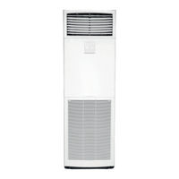
Floorstanding unit
Brand:
Daikin
| Category:
Air Conditioner
| Size: 4.09 MB
Table of Contents
Technical Data
1
Table of Contents
2
1 Features
3
2 Specifications
4
Technical Specifications
4
Electrical Specifications
5
3 Safety Device Settings
6
4 Options
7
5 Dimensional Drawings
8
6 Piping Diagrams
9
7 Wiring Diagrams
10
Wiring Diagrams - Single Phase
10
8 External Connection Diagrams
11
9 Sound Data
12
Sound Pressure Spectrum
12
Advertisement
Related Products
Daikin FVQ-C
Daikin FVQ71CVEB
Daikin FVQ125CVEB
Daikin FVQ100CVEB
Daikin FVQ71BV1B
Daikin FVQ125BV1B
Daikin FVQ100BV1B
Daikin FVQ71BV
Daikin FVKS50BVMB
Daikin FVXG35K
Daikin Categories
Air Conditioner
Heat Pump
Remote Control
Chiller
Air Handlers
More Daikin Manuals
Login
Sign In
OR
Sign in with Facebook
Sign in with Google
Upload manual
Upload from disk
Upload from URL