Sign In
Upload
Manuals
Brands
Daikin Manuals
Air Conditioner
FTXA20AW
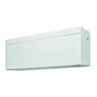
Daikin FTXA20AW Manuals
Manuals and User Guides for Daikin FTXA20AW. We have
2
Daikin FTXA20AW manuals available for free PDF download: Service Manual
Daikin FTXA20AW Service Manual (192 pages)
Split Stylish R32
Brand:
Daikin
| Category:
Air Conditioner
| Size: 9.09 MB
Table of Contents
Table of Contents
4
1 Troubleshooting
7
To Display the Error Code on the User Interface
7
To Reset the Error Code Via Remote Controller
7
To Reset the Error Code Via Outdoor Unit
7
To Perform a Test Run
7
To Perform a Test Run Using the User Interface
8
Error Based Troubleshooting
8
A1-00 - PCB Abnormality
8
A5-00 - Outdoor Unit: High Pressure Peak Cut / Freeze Protection Problem
9
A6-00 - Indoor Unit Fan Motor Abnormality
9
Streamer Unit Abnormality
10
C4-00 - Heat Exchanger Temperature Sensor Problem
10
C9-00 - Room Thermistor Abnormality
11
Humidity Sensor Abnormality
11
Intelligent Thermal Sensor Abnormality
12
E1-00 - Outdoor Unit: PCB Defect
12
E3-00 - Outdoor Unit: Actuation of High Pressure Switch
13
E5-00 - Outdoor Unit: Overheat of Inverter Compressor Motor
14
E6-00 - Outdoor Unit: Compressor Startup Defect
15
E7-00 - Outdoor Unit: Malfunction of Outdoor Unit Fan Motor
16
E8-00 - Outdoor Unit: Power Input Overvoltage
16
Outdoor Unit: Cool/Heat Switchover Problem
17
F3-00 - Outdoor Unit: Malfunction of Discharge Pipe Temperature
18
F6-00 - Outdoor Unit: Abnormal High Pressure in Cooling
19
F8-00 - System Shutdown Due to Compressor Internal Temperature Abnormality
20
H0-00 - Outdoor Unit: Voltage/Current Sensor Problem
20
H3-00 - Outdoor Unit: Malfunction of High Pressure Switch
21
H6-00 - Outdoor Unit: Malfunction of Position Detection Sensor
22
H8-00 - Outdoor Unit: Malfunction of Compressor Input System
23
H9-00 - Outdoor Unit: Malfunction of Outdoor Air Thermistor
23
J3-00 - Outdoor Unit: Malfunction of Discharge Pipe Thermistor
24
J6-00 - Outdoor Unit: Malfunction of Heat Exchanger Thermistor
24
L3-00 - Outdoor Unit: Electrical Box Temperature Rise Problem
24
L4-00 - Outdoor Unit: Malfunction of Inverter Radiating Fin Temperature Rise
25
L5-00 - Outdoor Unit: Inverter Instantaneous Overcurrent
26
P4-00 - Outdoor Unit: Malfunction of Radiating Fin Temperature Sensor
27
U0-00 - Outdoor Unit: Shortage of Refrigerant
27
U2-00 - Outdoor Unit: Defect of Power Supply Voltage
28
U4-00 - Indoor/Outdoor Unit Communication Problem
29
U5-00 - User Interface Communication Problem
30
Indoor Unit, Outdoor Unit Mismatching Problem
30
Symptom Based Troubleshooting
32
Operation Does Not Start
32
Operation Sometimes Stops
32
Operation Starts but the Unit Does Not Cool/Heat
33
Operating Noise and Vibrations
34
Abnormal High Pressure
35
Abnormal Low Pressure
36
Indoor Fan Starts Operating but the Compressor Does Not Operate
37
Operation Starts and the Unit Stops Immediately
38
Operation Stops, Unit Cannot Start for a While
38
Unit Discharges White Mist
39
Humidifying Problem
39
Swing Flap Does Not Operate
39
2 Components
40
4-Way Valve
40
Checking Procedures
40
Repair Procedures
43
Compressor
46
Checking Procedures
46
Repair Procedures
52
Expansion Valve
57
Checking Procedures
57
Repair Procedures
60
Front Panel Motor
65
Checking Procedures
65
Repair Procedures
66
High Pressure Switch
67
Checking Procedures
67
Repair Procedures
69
Humidity Sensor
70
Checking Procedures
70
Repair Procedures
71
Indoor Unit Fan Motor
73
Checking Procedures
73
Repair Procedures
73
Indoor Unit Main PCB
75
Checking Procedures
75
Repair Procedures
78
Indoor Unit Power PCB
81
Checking Procedures
81
Repair Procedures
84
Intelligent Thermal Sensor
88
Checking Procedures
88
Repair Procedures
88
Inverter PCB
89
Checking Procedures
89
Repair Procedures
91
Main PCB
91
Class 20~35 Units
91
Class 42~50 Units
99
Outdoor Unit Fan Motor
111
RXA20~35A3+5 Units
111
RXA20~35A2 + Class 42~50 Units
115
Plate Work
120
Outdoor Unit
120
Indoor Unit
126
Reactor
132
Checking Procedures
132
Repair Procedures
136
Streamer Unit
137
Checking Procedures
137
Repair Procedures
137
Swing Flap Motor
138
Main Swing Flap Motor
138
Secondary Swing Flap Motor
140
Swing Raster Motor
143
Checking Procedures
143
Repair Procedures
144
Thermistors
144
Refrigerant Side Thermistors
144
Other Thermistors
151
Wifi Control PCB
153
Checking Procedures
153
Repair Procedures
154
3 Third Party Components
156
Electrical Circuit
156
Checking Procedures
156
Repair Procedures
157
Refrigerant Circuit
158
Checking Procedures
158
Repair Procedures
162
External Factors
165
Checking Procedures
165
4 Maintenance
167
To Clean the Outdoor Unit Heat Exchanger
167
To Clean the Indoor Unit Heat Exchanger
167
To Clean the Indoor Unit Heat Exchanger in Extreme Condition
167
To Clean the Air Filters
168
5 Technical Data
170
Detailed Information Setting Mode
170
Detailed Information Setting Mode: Indoor Unit
170
Detailed Information Setting Mode: Outdoor Unit
170
Detailed Information Setting Mode: Remote Controller
170
Wiring Diagram
171
Wiring Diagram: Indoor Unit
171
Wiring Diagram: Outdoor Unit
173
Piping Diagram
176
Piping Diagram: Indoor Unit
176
Piping Diagram: Outdoor Unit
177
Component Overview
180
Component Overview: Indoor Unit
180
Component Overview: Outdoor Unit
182
Field Information Report
185
Service Tools
188
Field Settings
189
To Control Heating Only Mode
189
To Adjust Target Set Temperature in Heating Operation
189
To Control the Indoor Unit Fan During Thermostat off in Cooling
190
To Change Auto Restart on to off
190
To Control Cooling Mode Only
190
To Reduce Maximum Sound Levels
191
Advertisement
Daikin FTXA20AW Service Manual (168 pages)
Split R32
Brand:
Daikin
| Category:
Air Conditioner
| Size: 8.54 MB
Table of Contents
Table of Contents
4
1 Troubleshooting
7
To Display the Error Code on the User Interface
7
To Reset the Error Code Via Remote Controller
7
To Reset the Error Code Via Outdoor Unit
7
To Perform a Test Run
7
To Perform a Test Run Using the User Interface
8
Error Based Troubleshooting
8
A1-00 - PCB Abnormality
8
A5-00 - Freeze-Up Protection / Heating Peak Cut Control
9
A6-00 - Indoor Unit Fan Motor Abnormality
9
Streamer Unit Abnormality
10
C4-00 - Indoor Heat Exchanger Thermistor Abnormality
10
C9-00 - Room Thermistor Abnormality
11
Humidity Sensor Abnormality
11
Intelligent Thermal Sensor Abnormality
11
E1-00 - Outdoor Unit: PCB Defect
12
E3-00 - Outdoor Unit: Actuation of High Pressure Switch
13
E5-00 - Outdoor Unit: Overheat of Inverter Compressor Motor
14
E6-00 - Outdoor Unit: Compressor Startup Defect
15
E7-00 - Outdoor Unit: Malfunction of Outdoor Unit Fan Motor
16
E8-00 - Outdoor Unit: Power Input Overvoltage
16
Cooling/Heating Switch Abnormality
17
F3-00 - Outdoor Unit: Malfunction of Discharge Pipe Temperature
18
F6-00 - Outdoor Unit: Abnormal High Pressure in Cooling
18
F8-00 - System Shutdown Due to Compressor Internal Temperature Abnormality
19
H0-00 - Outdoor Unit: Voltage/Current Sensor Problem
20
H3-00 - Outdoor Unit: Malfunction of High Pressure Switch
20
H6-00 - Outdoor Unit: Malfunction of Position Detection Sensor
21
H8-00 - Outdoor Unit: Malfunction of Compressor Input System
22
H9-00 - Outdoor Unit: Malfunction of Outdoor Air Thermistor
23
J3-00 - Outdoor Unit: Malfunction of Discharge Pipe Thermistor
23
J6-00 - Outdoor Unit: Malfunction of Heat Exchanger Thermistor
23
L3-00 - Outdoor Unit: Electrical Box Temperature Rise Problem
24
L4-00 - Outdoor Unit: Malfunction of Inverter Radiating Fin Temperature Rise
25
L5-00 - Outdoor Unit: Inverter Instantaneous Overcurrent
25
P4-00 - Outdoor Unit: Malfunction of Radiating Fin Temperature Sensor
26
U0-00 - Outdoor Unit: Shortage of Refrigerant
27
U2-00 - Outdoor Unit: Defect of Power Supply Voltage
27
U4-00 - Indoor/Outdoor Unit Communication Problem
28
U5-00 - Transmission Malfunction between Indoor Unit and Remote Controller
29
Indoor Unit, Outdoor Unit Mismatching Problem
29
Symptom Based Troubleshooting
31
Operation Does Not Start
31
Operation Sometimes Stops
31
Operation Starts but the Unit Does Not Cool/Heat
32
Operating Noise and Vibrations
33
Abnormal High Pressure
34
Abnormal Low Pressure
35
Indoor Fan Starts Operating but the Compressor Does Not Operate
36
Operation Starts and the Unit Stops Immediately
37
Operation Stops, Unit Cannot Start for a While
37
Unit Discharges White Mist
38
Humidifying Problem
38
Swing Flap Does Not Operate
38
2 Components
39
4-Way Valve
39
Checking Procedures
39
Repair Procedures
42
Compressor
45
Checking Procedures
45
Repair Procedures
50
Expansion Valve
54
Checking Procedures
54
Repair Procedures
56
Front Panel Motor
61
Checking Procedures
61
Repair Procedures
62
High Pressure Switch
63
Checking Procedures
63
Repair Procedures
64
Humidity Sensor
66
Checking Procedures
66
Repair Procedures
66
Indoor Unit Fan Motor
68
Checking Procedures
68
Repair Procedures
68
Indoor Unit PCB
71
Checking Procedures
71
Repair Procedures
74
Intelligent Thermal Sensor
78
Checking Procedures
78
Repair Procedures
78
Inverter PCB
79
Checking Procedures
79
Repair Procedures
81
Main PCB
81
Checking Procedures
81
Repair Procedures
85
Outdoor Unit Fan Motor
89
RXA20~35A3+5 Units
89
RXA20~35A2 + Class 42~50 Units
93
Plate Work
99
Outdoor Unit
99
Indoor Unit
105
Reactor
109
Checking Procedures
109
Repair Procedures
110
Streamer Unit
112
Checking Procedures
112
Repair Procedures
112
Swing Flap Motor
113
Main Swing Flap Motor
113
Secondary Swing Flap Motor
116
Swing Raster Motor
118
Checking Procedures
118
Repair Procedures
119
Thermistors
119
Refrigerant Side Thermistors
119
Other Thermistors
125
Wifi Control PCB
129
Checking Procedures
129
Repair Procedures
129
3 Third Party Components
131
Electrical Circuit
131
Checking Procedures
131
Repair Procedures
132
Refrigerant Circuit
133
Checking Procedures
133
Repair Procedures
137
External Factors
140
Checking Procedures
140
Repair Procedures
141
4 Maintenance
142
To Clean the Outdoor Unit Heat Exchanger
142
To Clean the Indoor Unit Heat Exchanger
142
To Clean the Air Filters
142
5 Technical Data
144
Detailed Information Setting Mode
144
Detailed Information Setting Mode: Indoor Unit
144
Detailed Information Setting Mode: Outdoor Unit
144
Detailed Information Setting Mode: Remote Controller
144
Wiring Diagram
145
Wiring Diagram: Indoor Unit
145
Wiring Diagram: Outdoor Unit
147
Piping Diagram
151
Piping Diagram: Indoor Unit
151
Piping Diagram: Outdoor Unit
152
Component Overview
155
Component Overview: Indoor Unit
155
Component Overview: Outdoor Unit
157
Field Information Report
160
Service Tools
163
Field Settings
164
To Control Heating Only Mode
164
To Adjust Target Set Temperature in Heating Operation
164
To Control the Indoor Unit Fan During Thermostat off in Cooling
165
To Change Auto Restart on to off
165
To Control Cooling Mode Only
165
Advertisement
Related Products
Daikin FTXA20A2V1BW
Daikin FTXA20A2V1BS
Daikin FTXA20A2V1BT
Daikin FTXA20A2V1B
Daikin FTXA20AS
Daikin FTXA20AT
Daikin FTXA20A
Daikin FTXA20AB2V1BS
Daikin FTXA20AB2V1BT
Daikin FTXA20BB
Daikin Categories
Air Conditioner
Heat Pump
Remote Control
Chiller
Air Handlers
More Daikin Manuals
Login
Sign In
OR
Sign in with Facebook
Sign in with Google
Upload manual
Upload from disk
Upload from URL