Sign In
Upload
Manuals
Brands
Daikin Manuals
Air Conditioner
FTX35JVEA9
Daikin FTX35JVEA9 Manuals
Manuals and User Guides for Daikin FTX35JVEA9. We have
2
Daikin FTX35JVEA9 manuals available for free PDF download: Service Manual
Daikin FTX35JVEA9 Service Manual (410 pages)
Super Multi Plus J Series
Brand:
Daikin
| Category:
Heat Pump
| Size: 12.38 MB
Table of Contents
Table of Contents
4
Introduction
10
Safety Cautions
10
Part 1 List of Function
14
List of Function
15
Function List for General
15
Function List for China
16
Function List for Taiwan
17
Function List for Europe
18
Function List for Singapore, Malaysia, Indonesia
19
Function List for Australia
20
Function List for Europe
21
Part 2 Specifications
22
Outdoor Units
23
Outdoor Unit
24
Indoor Unit
24
Heat Pump
27
BP Units
31
Indoor Units (for General)
32
Duct Connected Type
35
Indoor Units (for China)
47
Indoor Units (for Taiwan)
56
Indoor Units (for Europe)
65
Floor Standing Type
70
Part 3 Printed Circuit Board Connector Wiring Diagram and Name
72
Printed Circuit Board Connector Wiring Diagram and Name
73
Branch Provider Unit BPMK928B42, B43
73
Outdoor Unit RMK (X) 140JVMT (C) 9 (8), RMK140JAVM, RMX140JVMB, RMK (X) 140JZVMA (B)
74
Outdoor Unit RMK (X) 140JVMT (C) 9 (8), RMK140JAVM
74
Rmx140Jvmb, Rmk (X) 140Jzvma (B)
74
FTK25 / 35J Series, FTX25 / 35J Series, FTXD25 / 35K Series, FVX25 / 35K Series
77
FTK50~60HV Series, FTKD50~71JV Series, FTX50~60HV Series, FTXD50~71JV Series
79
CDX25~60HAV Series, CDK25~60HAV Series
81
FLK25~60HV Series, FLX25~60HV Series, FLK50 / 60JV Series, FLX50 / 60JV Series
83
FHYC35~71KV Series
86
FDYM60FA, FDYM03FA Series
88
Part 4 Main Functions Indoor Unit
90
Main Functions
91
Main Functions in Split Type
91
Fan Speed Control for Indoor Units
97
Program Dry Function
100
Night Set Mode
102
Intelligent Eye
103
Program Dry Operation
105
Freeze Protection Function
107
Powerful Operation
109
Skyair
111
Cautions When Skyair [Auto] [FAN] Are Used
113
Part 5 Main Functions Outdoor Unit / BP Unit
114
Refrigerant System and Function of Functional Parts of Outdoor Unit
116
Of Outdoor Unit
116
Major Functional Parts
117
Protective Devices, Thermistors, Sensors
119
Protection Device
120
Outdoor Unit
120
BP Unit
121
System Control
122
Outline of System Control
122
Mode Configuration
123
Standby Control at Power on
124
Cooling / Heating Standby Operation at Startup
125
Equalizing Control
126
Determination of Initial Frequency
128
Oil Return Operation
133
Defrost Operation
135
PART 5 3.8 Defrost Operation
135
Pre-Equalization Standby Operation
136
Equalizing Control
137
Capacity Control
139
Peak Cut Control
141
Freeze-Up Prevention
142
Gas Shortage Malfunction
143
Discharge Pipe Control
144
Input Current Control
145
Wet Protection Control I
148
Electric Parts Cooling and Electric Parts / Fin Temperature Control
149
Differential Pressure Control
150
Year-Round Cooling-Only Function
151
Nighttime Low Noise Control
152
PI Control
153
Warm-Up Function
154
Compressor Protection Control
155
Fan Control
156
Motorized Valve Control of Outdoor Unit
158
Cooling Outdoor Unit SC Control
164
BP Unit Motorized Valve Control
165
Gas Pipe Isothermal Control in Cooling Operation
168
SH Control in Cooling Operation
170
SC Control in Heating Operation
172
Heat Exchanger Isothermal Control in Heating Operation
174
BP Unit Motorized Valve Control in High Discharge Pipe Temperature
175
Inter-BP Units Heating Heat Exchanger Isothermal Control
176
Inter-BP Units Gas Pipe Isothermal Control
177
BP Unit Motorized Valve Control by Target Discharge Pipe Temperature
178
4-Way Valve Operation
179
JIS Mode
180
Pump down Operation
181
Protection Control of Skyair Indoor Units
182
Part 6 Flow of Refrigerant
184
Flow of Refrigerant
185
Standby Operation (Cooling)
186
Equalizing Control (Cooling)
187
Oil Return Operation (Cooling)
188
Low Outside Air Temperature Cooling
189
All-Room Operation (Cooling)
190
Multi-Room Operation (no Surplus Refrigerant) (Cooling)
191
Multi-Room Operation (Cooling) (with Surplus Refrigerant)
192
1-Room Operation - Indoor Unit with Large Capacity (Cooling)
193
1-Room Operation - Indoor Unit with Small Capacity (2.5 Kw) (Cooling)
194
Standby Operation (Heating)
195
Equalizing Control (Heating)
196
Oil Return Operation (Heating)
197
1.14 Defrost Operation
198
All-Room Operation (Heating)
199
Multi-Room Operation (with Non-Operating Room Unit) (Heating)
200
Multi-Room Operation (Heating)
201
1-Room Operation - Indoor Unit with Large Capacity (Heating)
202
1-Room Operation - Indoor Unit with Small Capacity (2.5 Kw) (Heating)
203
Part 7 Operations
204
Remote Controller
205
Wireless Remote Controller
205
Si18
214
Wired Remote Controller
215
Part 8 Operating Test
218
Operating Test
219
Test Operation Switch
222
Pump down Operation Switch
223
Record of the Installation Position
224
Method of Field Set
225
Field Setting
225
Initial Setting Contents
226
Detailed Explanation of Setting Modes
228
Group Number Setting for Central Remote Control
233
Interface Adaptor for Room Airconditioner <KRP928A1S
234
Precautions: for RMK140J / RMX140J Outdoor Unit Users
236
Part 9 Service Diagnosis
238
Troubleshooting - Split Type Indoor Unit
239
Troubleshooting with the Operation Lamp
239
Service Check Function
241
Code Indication on the Remote Controller
243
Troubleshooting
244
Troubleshooting Detail
245
Troubleshooting - Skyair Indoor Unit
259
The INSPECTION/TEST Button
259
Self-Diagnosis by Wired Remote Controller
260
Fault Diagnosis by Wireless Remote Controller
261
Troubleshooting by LED on the Indoor Unit's
263
Troubleshooting by Remote Controller Display / LED Display
264
Troubleshooting Detail
265
Indoor Unit Fan Motor Lock
268
Troubleshooting - Outdoor Unit Related
273
The Unit Runs but Doesn't Cool (Heat) the Room
273
Seg. Display on the Outdoor P. C. Board
275
Troubleshooting Detail
276
Compressor Lock
277
Transmission Error between Outdoor Unit and Bp Unit
304
Transmission Error between Indoor Unit and Bp Unit
306
How to Check
313
Service Diagnosis
315
Thermistor Resistance Check
318
Power Supply Waveforms Check
321
BP Unit Trouble Diagnosis
323
PCB Parts Layout
323
LED on Branch Provider Unit (Diagnosis Leds)
323
Part 10 Removal Procedure
324
For BPMK928B42 · 43
325
Installation of Indoor Unit
325
Opening of Electrical Box Cover and Removal of PCB Mount
326
Removal of Motorized Valve
328
Removal of Thermistor
331
Outdoor Unit
333
Removal of Outer Panels
333
Removal of PCB and Electrical Box
334
Removal of Propeller Fans and Fan Motors
342
Removal of Thermistor
344
Removal of Motorized Valve
345
Removal of Sound Insulation
347
Removal of Compressor
349
Removal of 4-Way Valve
351
Indoor Unit
355
Refer Following Table for Indoor Unit Removal Procedure
355
Part 11 Cautions before Operation
356
Installation
357
Outdoor Unit
357
BP Unit
359
Wiring
361
Outdoor Unit
361
BP Unit
363
Outdoor Unit Rotary Switch Setting
365
Others
367
Explanation for FTK(X)25/35J Series
367
Centralized Control
368
Explanation for FTK(X)50/60H and CDK(X)25~60H Series
370
Part 12 Appendix
372
Piping Diagrams
373
Outdoor Units
373
BP Units
375
Indoor Units
376
Wiring Diagrams
383
Outdoor Units
383
BP Units
387
Indoor Units
388
Index
402
Advertisement
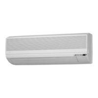
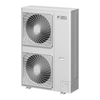
Daikin FTX35JVEA9 Service Manual (162 pages)
Inverter Pair FTK(X)-J / RK(X)-J Series
Brand:
Daikin
| Category:
Air Conditioner
| Size: 5.19 MB
Table of Contents
Table of Contents
3
Part 1 List of Function
3
Part 3 Printed Circuit Board Connector Wiring Diagram
3
Part 5 System Configuration
3
Part 6 Service Diagnosis
3
Introduction
6
Safety Cautions
6
Caution in Repair
6
Cautions Regarding Products after Repair
7
Inspection after Repair
8
Using Icons
9
Using Icons List
9
Part 1 List of Function
10
Functions
11
Indoor Unit and Outdoor Unit
11
Part 2 Specification
12
Specifications
13
Cooling Only
13
Specifications
14
Heat Pump
17
Part 3 Printed Circuit Board Connector Wiring Diagram
20
Printed Circuit Board Connector Wiring Diagram and Name
21
FTK25/35J Series, FTX25/35J Series
21
Control Pcb
22
RK25/35J Series, RX25/35J Series
24
Part 4 Main Function
26
General Functionality
27
Functions of Thermistors
27
Operating Modes
29
Frequency Principle
30
Defrost Control
32
Forced Operation Mode
33
Wide-Angle Flaps, Diffuser, Louveres and Autoswing
34
Fan Speed Control for Indoor Units
35
Fan Speed Control for Outdoor Units
36
General Functions
37
Intelligent Eye
39
Good Sleep Cooling Control
41
Automatic Operation
42
Input Current Control
43
Freeze Protection Function in Cooling
44
Peak-Cut Control Function
45
Four-Way Valve Function Compensation
46
Compressor Protection Function
47
Wet Operation Protection
48
Dew Condensation Sweating Prevention Function
49
Part 5 System Configuration
50
Instruction
51
Ftk25 / 35J, Ftx25 / 35J
51
Safety Precautions
51
Names of Parts
53
Preparation before Operation
55
Setting the Clock
56
Tips for Saving Energy
56
Powerful Operation
58
Adjusting the Air Flow Direction
59
Timer Operation
60
Care and Cleaning
63
Before a Long Idle Period
64
Trouble Shooting
65
Fault Diagnosis
68
System Configuration
68
Part 6 Service Diagnosis
70
Caution for Diagnosis
71
Troubleshooting with the Operation Lamp
71
Problem Symptoms and Measures
72
Service Check Function
73
ARC423 Series
73
Code Indication on the Remote Controller
74
Error Codes and Description of Fault
74
Trouble Shooting
75
Faulty PCB
75
Operation Shutdown Due to High-Pressure Control or Freeze-Up Protection (Thermistor Activation)
76
Operation Halt Due to Fan Motor (AC Motor) or Related Abnormality
77
Operation Halt Due to Detection of Thermistor or Related Abnormality
78
Faulty Indoor Unit PCB
79
Faulty Indoor Unit PCB
80
Power Supply Abnormalities or Faulty Indoor Printed Circuit Boards
81
Signal Transmission Error (between Indoor and Outdoor Units)
82
Operation Halt Due to Detection of CT Error
83
Operation Halt Due to Thermistor Error or Disconnection Detection
84
Operation Halt Due to Compressor Startup Error
85
Output Overcurrent
86
Troubleshooting
87
Faulty Outdoor Unit PCB
88
Faulty Outdoor Unit PCB and Transmitting/Receiving Circuit
89
Operation Halt Due to Detection of Input over Current
90
Interrupt Due to OL Action
92
Check
94
How to Check
94
Power Transistor Check
94
Capacitor Voltage Check
94
Thermistor Resistance Check
97
Installation Condition Check
98
Discharge Pressure Check
99
Rectifier Check
99
Power Supply Waveforms Check
100
Hall IC Check
101
Refrigerant System Check
101
Part 7 Removal Procedure
102
For FTK25J, FTK35J, FTX25J, FTX35J
103
Removal of Air Filter
103
Removal of Front Grille
106
Removal of Horizontal Blade and Vertical Blade
109
Removal of Switch Box, PC Board and Swing Motor
111
Removal of Heat Exchanger
117
Install of Drain Plug
120
Removal of Fan Rotor and Motor
121
Si04
124
For RK25J, RK35J, RX25J, RX35J
125
Removal of External Casing
125
Removal of Bell Mouth and Left Side Plate
128
Removal of PC Board and Switch Box
129
Removal of Propeller Fan and Fan Motor
135
Removal of Compressor Noise Absorption Pad
137
Removal of Partition Plate and Reactor
139
Removal of Four-Way Valve
141
Removal of Compressor
143
Part 8 Others
147
Others
147
Explanation
147
Part 9 Appendix
150
Piping Diagram
151
Indoor Unit
151
Outdoor Unit
152
Wiring Diagram
154
Indoor Unit
154
Outdoor Unit
156
Index
158
Advertisement
Related Products
Daikin FTX35J2V1B
Daikin FTX35JV1B
Daikin FTX35JVET9
Daikin FTX35JV1NB9
Daikin FTX35JV
Daikin FTX35JEVM
Daikin FTX35J3V1B
Daikin FTX35GV1B
Daikin FTX35K5V1B
Daikin FTX35AMVMC
Daikin Categories
Air Conditioner
Heat Pump
Remote Control
Chiller
Air Handlers
More Daikin Manuals
Login
Sign In
OR
Sign in with Facebook
Sign in with Google
Upload manual
Upload from disk
Upload from URL