Sign In
Upload
Manuals
Brands
Daikin Manuals
Heat Pump
ERQ
Daikin ERQ Manuals
Manuals and User Guides for Daikin ERQ. We have
2
Daikin ERQ manuals available for free PDF download: Service Manual, Installation Manual
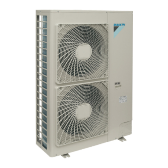
Daikin ERQ Service Manual (260 pages)
ERQ 100/125/140 A7V1B (outdoor unit) EKEQD/F/MCBV3 (control box) EKEXV 50/63/80/100/125/140 (expansion valve kit)
Brand:
Daikin
| Category:
Heat Pump
| Size: 13.3 MB
Table of Contents
Table of Contents
3
Service Manual
1
Introduction
7
Safety Cautions
7
Part 1 General Information
11
1 Model Names of Outdoor Units, Control Box and Expansion Valve Kit
12
Outdoor Units
12
Control Box
13
Expansion Valve Kit
14
2 Combination Table
15
Esie09
15
Part 2 Specifications
17
Specifications
18
Outdoor Units
18
Air Handling Units
21
Part 3 List of Electrical and Functional Parts
23
List of Electrical and Functional Parts
24
Outdoor Unit
24
Part 4 Refrigerant Circuit
25
1 Refrigerant Circuit
26
Outdoor Unit
26
2 Functional Parts Layout
28
Erq 100/125/140 A7V1B
28
Back View
29
Part 5 Function
31
1 Operation Mode
32
2 Basic Control
33
Normal Operation
33
Compressor PI Control
34
Cooling Operation Fan Control
35
3 Special Control
36
Startup Control
36
Oil Return Operation
37
Defrosting Operation
39
Pump-Down Residual Operation
40
Restart Standby
41
Stopping Operation
42
4 Protection Control
43
High Pressure Protection Control
43
Low Pressure Protection Control
44
Discharge Pipe Protection Control
45
Inverter Protection Control
46
5 Other Control
47
Demand Operation
47
Heating Operation Prohibition
47
6 Outline of Control
48
Thermostat Sensor in Remote Controller (Only for Z-Control)
48
Freeze Prevention
50
Hot Start Control (in Heating Operation Only)
51
Part 6 Control Box Ekeq - Cbv3
53
1 Different Systems with Their Control Boxes
54
System A: PAIR
54
System B: MULTI
56
2 X, Y, Z Control
59
X-Control
59
Y-Control
60
Z-Control
61
3 Wiring Diagram of Control Box
62
D-Box
62
F-Box
63
4 Attention Points
64
System A: EKEQF & EKEQD-Box: Installation and Operation Manual
65
5 System A: EKEQF & EKEQD-Box: Installation and Operation Manual.55
65
6 System B: EKEQM-Box: Installation and Operation Manual
80
Part 7 Test Operation
93
1 Test Operation
94
Procedure and Outline
94
Air Tight Test and Vacuum Drying
95
Operation When Power Is Turned on
100
2 Outdoor Unit PC Board Layout
101
3 Field Setting
102
Field Setting from Remote Controller
102
Field Setting from Outdoor Unit
110
Part 8 Installation and Operation Manual
127
Installation Manual
128
Installation Manual
131
1 Safety Considerations
131
2 Introduction
132
Combination
132
Standard Supplied Accessories
133
Technical and Electrical Specifications
133
3 Before Installation
133
Precautions for R410A
133
Installation
133
Handling
133
4 Selecting Installation Site
133
5 Precautions on Installation
134
Installation Method for Prevention of Falling over
135
Method for Removing Transportation Stay
135
Method for Installing Drain Piping
135
6 Installation Servicing Space
135
7 Refrigerant Pipe Size and Allowable Pipe Length
136
Selection of Piping Material
136
8 Precautions on Refrigerant Piping
136
Cautions for Brazing
137
Cautions for Flare Connection
137
9 Refrigerant Piping
137
Preventing Foreign Objects from Entering
138
Cautions for Handling Stop Valve
138
How to Use the Stop Valve
138
Cautions for Handling the Valve Cover
138
Cautions for Handling Service Port
138
Precautions When Connecting Field Piping and
139
Regarding Insulation
139
Leak Test and Vacuum Drying
139
10 Additional Refrigerant Charge
139
Important Information Regarding the Refrigerant Used
140
Procedures for Adding Refrigerant
141
11 Electrical Wiring Work
141
Internal Wiring - Parts Table
141
Precautions on Electrical Wiring Work
142
Connection Example of Total System Wiring
143
Connecting Power Wire and Transmission Wires
143
Power Circuit and Cable Requirements
143
12 Before Operation
145
Service Precautions
145
Checks before Initial Start-Up
145
Field Setting
145
Test Operation
147
Checks in Normal Operation
148
Temperature Adjustment Operation Confirmation
148
13 Service Mode Operation
148
14 Caution for Refrigerant Leaks
149
Introduction
149
Maximum Concentration Level
149
Procedure for Checking Maximum Concentration
149
15 Disposal Requirements
149
Operation Manual
152
Safety Cautions
152
Important Information Regarding the Refrigerant Used
153
What to Do before Operation
153
Changeover Switch: Name and Function of each Switch
154
Operation Procedure
154
Cooling, Heating, and Fan Only Operation
154
Operation Range
154
Remote Controller
154
Energy Saving and Optimum Operation
155
Following Symptoms Are Not Air Conditioner Troubles
155
Maintenance
155
Maintenance after a Long Stop Period
155
Maintenance before a Long Stop Period
155
Troubleshooting
156
After-Sales Service and Warranty
157
After-Sales Service
157
Shortening of "Maintenance Cycle" and "Replacement Cycle" Needs to be Considered in Following Situations
157
Part 9 Troubleshooting
159
Symptom-Based Troubleshooting
161
Troubleshooting by Remote Controller
164
The INSPECTION / TEST Button
164
Self-Diagnosis by Wired Remote Controller
165
Remote Controller Service Mode
166
Remote Controller Self-Diagnosis Function
168
Troubleshooting by Indication on the Remote Controller
175
A0" AHU: Error of External Protection Device
175
A1" AHU: PC Board Defect
176
A6" AHU: Fan Motor (M1F) Lock, Overload
177
Abnormal Power Supply Voltage
178
A9" AHU: Malfunction of Moving Part of Electronic Expansion Valve (Y1E)
179
AJ" AHU: Malfunction of Capacity Determination Device
181
C1" AHU: Failure of Transmission (between AHU PC Board and Fan PC Board)
182
C4" AHU: Malfunction of Thermistor (R2T) for Heat Exchanger
184
C5" AHU: Malfunction of Thermistor (R3T) for Gas Pipes
185
Board)
186
C9" AHU: Malfunction of Thermistor (R1T) for Suction Air
187
CA" AHU: Malfunction of Thermistor for Discharge Air
188
CC" AHU: Malfunction of Humidity Sensor System
189
CJ" AHU: Malfunction of Thermostat Sensor in Remote Controller
190
E1" Outdoor Unit: PC Board Defect
191
E3" Outdoor Unit: Actuation of High Pressure Switch
192
E4" Outdoor Unit: Actuation of Low Pressure Sensor
194
E5" Inverter Compressor Motor Lock
196
E7" Malfunction of Outdoor Unit Fan Motor
197
E9" Outdoor Unit: Malfunction of Moving Part of Electronic Expansion Valve (Y1E, Y3E)
198
Valve (Y1E, Y3E)
198
F3" Outdoor Unit: Abnormal Discharge Pipe Temperature
200
F6" Outdoor Unit: Refrigerant Overcharged
201
H9" Outdoor Unit: Malfunction of Thermistor (R1T) for Outdoor Air
202
J3" Outdoor Unit: Malfunction of Discharge Pipe Thermistor (R2T)
203
J5" Outdoor Unit: Malfunction of Thermistor (R3T, R5T) for Suction Pipe 1, 2
204
J6" Outdoor Unit: Malfunction of Thermistor (R6T)
205
J7" Outdoor Unit: Malfunction of Thermistor (R7T) for Outdoor Unit Liquid Pipe
206
J9" Outdoor Unit: Malfunction of Thermistor (R4T)
207
JA" Outdoor Unit: Malfunction of High Pressure Sensor
208
JC" Outdoor Unit: Malfunction of Low Pressure Sensor
209
L1" Outdoor Unit: Malfunction of PC Board
210
L4" Outdoor Unit: Malfunction of Inverter Radiating Fin Temperature Rise
211
L5" Outdoor Unit: Inverter Compressor Abnormal
212
L8" Outdoor Unit: Inverter Current Abnormal
213
L9" Outdoor Unit: Inverter Start up Error
214
LC" Outdoor Unit: Malfunction of Transmission between Inverter and Control PC Board
215
P1" Outdoor Unit: High Voltage of Capacitor in Main Inverter Circuit
216
U0" Low Pressure Drop Due to Refrigerant Shortage or Electronic Expansion Valve Failure
217
U2" Power Supply Insufficient or Instantaneous Failure
219
U3" Check Operation Not Executed
221
U4" Malfunction of Transmission between Ahus and Outdoor Units
222
U5" Malfunction of Transmission between Remote Controller and AHU
224
UA" Excessive Number of Ahus
225
UF" System Is Not Set yet
226
UH" Malfunction of System, Refrigerant System Address Undefined
227
Troubleshooting by Indication on the Unified ON/OFF Controller
228
Operation Lamp Blinks
228
Display "Under Host Computer Integrate Control" Blinks (Repeats Single Blink)
230
Display "Under Host Computer Integrate Control" Blinks (Repeats Double Blink)
233
Part 10 Appendix
237
Piping Diagrams
238
Outdoor Unit
238
Wiring Diagrams
239
Outdoor Unit
239
Field Wiring
240
Option List
241
Thermistor Resistance / Temperature Characteristics
242
Pressure Sensor
244
Method of Replacing the Inverter's Power Transistors Modules
245
Part 11 Precautions for New Refrigerant (R-410A)
247
Precautions for New Refrigerant (R-410A)
248
Outline
248
Refrigerant Cylinders
250
Service Tools
251
Advertisement
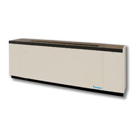
Daikin ERQ Installation Manual (42 pages)
Self-Contained Water Source Heat Pump Unit Ventilator
Brand:
Daikin
| Category:
Heat Pump
| Size: 9.48 MB
Table of Contents
Table of Contents
3
Nomenclature
4
Data Plate - Specific Information
4
Data Plate Location
5
Models ARQ, ERQ, GRQ Self-Contained Floor Unit Ventilator Installation
5
Receiving & Handling
5
Visible Loss or Damage
5
Concealed Loss or Damage
5
Storage
5
Lifting Unit
5
General Unit Data
5
Safety
6
Pre-Installation Considerations
6
Uncrate and Inspect the Unit Ventilator(S)
6
Typical Floor Unit Installation
7
Typical Ventimatic Shutter Installation
7
Meeting IBC Seismic Requirements
8
Wall Openings, Louvers & Venitmatic Shutter
9
Louver Installations with Typical Unit Arrangements
10
16-5/8" Unit Depth
10
21-7/8" Unit Depth
11
Unit Depth
12
Installing Louvers
12
Installing the Ventimatic Shutter Assembly
14
Preparing to Move the Unit
16
Removing Unit from Skid
16
Unit Ventilator Installation
16
Before Sliding the Unit into Place
16
Installing Casters
16
Reversing Condensate Drain End
17
Mounting Hole Locations & Dimensions
17
Operating Limits
19
Piping Considerations
20
Water System Cleaning
21
Make Piping Connections
22
Water Coil Connections
22
System Balancing
23
Making Control Connections
24
Microtech II Unit-Mounted DDC Control Components
24
Typical Wiring Diagram
27
DX Cooling with Electric Heat, Valve Control 460V, 3 Phase
27
Electical Data
28
Size 024
28
Size 040
28
Size 048
29
Microtech II Unit Electical Connections
30
Microtech II Remote Wall-Mounted Sensor
32
Electromechanical Unit Wire Connections
36
Installing (Optional) End Panel
37
Piping Stub-Up Details, 6' End Panel
38
End Panel Assembly, 1" and 6" End Panel
38
Prepare Unit Ventilator for Start-Up
39
Post Installtion Checklist
39
Oiling
39
Filters
39
Prepare for Start-Up
40
Complete Check, Test and Start Procedure
40
Troubleshooting
41
The in and Outs of R-410A
41
Lubrication
41
Charging
41
General Maintenance
41
Troubleshooting Refrigeration Circuit
42
Advertisement
Related Products
Daikin ERQ125A7W1B
Daikin ERQ200A7W1B
Daikin ERQ250A7W1B
Daikin ERQ-AW1
Daikin ERRQ 011AAV1
Daikin altherma ERHQ014BAV3
Daikin ERGA04EAV3A
Daikin ERGA08E
Daikin ERHQ008BBV3
Daikin ERLA-DV17
Daikin Categories
Air Conditioner
Heat Pump
Remote Control
Chiller
Air Handlers
More Daikin Manuals
Login
Sign In
OR
Sign in with Facebook
Sign in with Google
Upload manual
Upload from disk
Upload from URL