Sign In
Upload
Manuals
Brands
Daikin Manuals
Air Conditioner
2MXS40GV1B
Daikin 2MXS40GV1B Manuals
Manuals and User Guides for Daikin 2MXS40GV1B. We have
2
Daikin 2MXS40GV1B manuals available for free PDF download: Service Manual, Service Manual Removal Procedure
Daikin 2MXS40GV1B Service Manual (341 pages)
Inverter Multi for 2 Rooms G-Series
Brand:
Daikin
| Category:
Air Conditioner
| Size: 19.3 MB
Table of Contents
Table of Contents
3
Introduction
7
Safety Cautions
7
Used Icons
11
Part 1 List of Functions
12
Functions
13
Cooling Only
13
Function and Control Part
15
Heat Pump
16
Part 2 Specifications
21
Specifications
22
Cooling Only - Indoor Unit
22
Cooling Only - Outdoor Unit
29
Heat Pump - Indoor Unit
31
Heat Pump - Outdoor Unit
40
Part 3 Printed Circuit Board Connector Wiring Diagram
42
Indoor Unit
43
Wall Mounted Type
43
Floor Standing Type
51
Floor / Ceiling Suspended Dual Type
53
Duct Connected Type
55
Ceiling Mounted Cassette Type
57
Remote Controller
59
Wired Remote Controller
59
Wireless Remote Controller
60
Outdoor Unit
61
2Mk(X)S40/50Gv1B, 2Mk(X)S40/50G2V1B
61
Part 4 Function and Control
63
Function of Indoor Unit (RA Models)
64
Temperature Control
64
Frequency Principle
64
Operation Starting Control
66
Airflow Direction Control
67
Fan Speed Control for Indoor Units
69
Program Dry Operation
70
Automatic Operation
71
Thermostat Control
72
NIGHT SET Mode
74
ECONO Operation
75
HOME LEAVE Operation
76
2-Area INTELLIGENT EYE Operation
77
INTELLIGENT EYE Operation
79
Inverter POWERFUL Operation
80
Other Functions
82
Function of Indoor Unit (SA Models)
84
Drain Pump Control
84
Thermostat Sensor in Remote Controller
86
Freeze Prevention Control
88
Hot Start Control (in Heating Operation Only)
89
Function of Thermistor
90
Control Specification
92
Mode Hierarchy
92
Frequency Control
94
Controls at Mode Changing / Start-Up
97
Discharge Pipe Temperature Control
98
Compressor Protection Function
98
Input Current Control
99
Freeze-Up Protection Control
99
Heating Peak-Cut Control
100
Outdoor Fan Control
100
Liquid Compression Protection Function
101
Defrost Control
101
Electronic Expansion Valve Control
102
Malfunctions
106
Part 5 Operation Manual
109
System Configuration
110
RA Indoor Unit
111
FTXG-J, CTXG-J Series - ARC466A1
111
Fan Operation
115
Operating Conditions
116
FTXS, FVXS Series - ARC452A1, A3
133
Names of Parts
137
Opening the Front Panel
137
FTXG-E, CTXG-E, FLK(X)S, FDK(X)S Series
160
Arc433B41, B67, B68, B69, B76
160
FTXG-E, CTXG-E, FLK(X)S, FDK(X)S Series ARC433B41, B67, B68, B69, B76
160
Adjusting the Air Flow Direction
166
SA Indoor Unit - FFQ Series
179
Brc1D528
179
Brc7E530W/531W
194
Names and Functions
195
Operation Range
197
Operation Procedure
198
Part 6 Service Diagnosis
206
Troubleshooting with LED
208
Indoor Unit
208
Outdoor Unit
209
Problem Symptoms and Measures
210
Service Check Function
211
SA Indoor Unit - FFQ Series
220
RA Indoor Unit - F(C)TXG, FTXS, FVXS, FLK(X)S
224
FDK(X)S Series
224
Code Indication on Remote Controller
224
RA Indoor Unit - F(C)TXG, FTXS, FVXS, FLK(X)S, FDK(X)S Series
224
SA Indoor Unit - FFQ Series
224
Outdoor Unit
225
Troubleshooting for RA Indoor Unit - F(C)TXG, FTXS, FVXS, FLK(X)S, FDK(X)S Series
226
Indoor Unit PCB Abnormality
226
Freeze-Up Protection Control or Heating Peak-Cut Control
227
Fan Motor or Related Abnormality
229
Thermistor or Related Abnormality (Indoor Unit)
232
Front Panel Open / Close Fault (FTXG, CTXG)
233
Troubleshooting for SA Indoor Unit - FFQ Series
234
Indoor Unit PCB Abnormality
234
Drain Water Level System Abnormality
235
Fan Motor or Related Abnormality
237
Drain System Abnormality
238
Thermistor or Related Abnormality
239
Remote Controller Thermistor Abnormality
241
Signal Transmission Error
242
(Between Indoor Unit and Remote Controller)
242
Signal Transmission Error (between Indoor Unit and Remote Controller)
242
Signal Transmission Error
243
(Between MAIN Remote Controller and SUB Remote Controller)
243
Signal Transmission Error (between MAIN Remote Controller and SUB Remote Controller)
243
Field Setting Abnormality
244
Troubleshooting for Outdoor Unit
246
Anti-Icing Control for Indoor Unit
246
OL Activation (Compressor Overload)
248
Compressor Lock
249
DC Fan Lock
250
Input Overcurrent Detection
251
Discharge Pipe Temperature Control
252
High Pressure Control in Cooling
253
Compressor Sensor System Abnormality
254
Position Sensor Abnormality
255
DC Voltage / Current Sensor Abnormality
257
Thermistor or Related Abnormality (Outdoor Unit)
258
Electrical Box Temperature Rise
260
Radiation Fin Temperature Rise
261
Output Overcurrent Detection
263
Refrigerant Shortage
265
Low-Voltage Detection or Over-Voltage Detection
267
Outdoor Unit PCB Abnormality or Signal Transmission Error
268
Unspecified Voltage (between Indoor Unit and Outdoor Unit) / Anti-Icing Control in Other Room
271
Check
272
Thermistor Resistance Check
272
Fan Motor Connector Output Check
273
Hall IC Check
273
Power Supply Waveforms Check
273
Electronic Expansion Valve Check
274
Four Way Valve Performance Check
275
Inverter Unit Refrigerant System Check
276
Inverter Checker" Check
277
Rotating Pulse Input on the Outdoor Unit PCB Check
279
Installation Condition Check
280
Discharge Pressure Check
280
Outdoor Unit Fan System Check
281
Main Circuit Short Check
281
Power Module Check
282
Part 7 Removal Procedure
283
Outdoor Unit
284
Removal of Outer Panels
284
Removal of Electrical Box
286
Removal of PCB
291
Removal of Sound Blankets
296
Removal of Outdoor Fan / Fan Motor
298
Removal of Thermistors
301
Removal of Four Way Valve / Electronic Expansion Valves
303
Removal of Compressor
306
Part 8 Trial Operation and Field Settings
308
Pump down Operation
309
Forced Cooling Operation
310
Trial Operation
311
RA Indoor Unit - F(C)TXG, FTXS, FVXS, FLK(X)S
311
FDK(X)S Series
311
RA Indoor Unit - F(C)TXG, FTXS, FVXS, FLK(X)S, FDK(X)S Series
311
SA Indoor Unit - FFQ Series
313
Field Settings
314
RA Indoor Unit - F(C)TXG, FTXS, FVXS, FLK(X)S
314
FDK(X)S Series
314
Model Type Setting
314
RA Indoor Unit - F(C)TXG, FTXS, FVXS, FLK(X)S, FDK(X)S Series
314
When 2 Units Are Installed in 1 Room
314
Jumper and Switch Settings
317
SA Indoor Unit - FFQ Series
318
Outdoor Unit
325
Jumper Settings
325
Application of Silicon Grease to a Power Transistor and a Diode Bridge
326
Part 9 Appendix
327
Piping Diagrams
328
Indoor Unit
328
Outdoor Unit
332
Wiring Diagrams
334
Indoor Unit
334
Outdoor Unit
338
Advertisement
Daikin 2MXS40GV1B Service Manual Removal Procedure (29 pages)
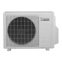
Outdoor Unit 4.0/5.0 kW Class
Brand:
Daikin
| Category:
Air Conditioner
| Size: 5.77 MB
Table of Contents
Table of Contents
3
Removal of Outer Panels
4
Removal of Electrical Box
6
Removal of PCB
11
Removal of Sound Blankets
16
Removal of Outdoor Fan / Fan Motor
18
Removal of Thermistors
21
Removal of Four Way Valve / Outdoor Electronic Expansion Valves
23
Removal of Compressor
26
Advertisement
Related Products
Daikin 2MXS40G2V1B
Daikin 2MXS40BVMB
Daikin 2MXS40DVMB
Daikin 2MXS40FV1B
Daikin 2MXS40H3V1B2
Daikin 2MXS18NMVJU
Daikin 2MXS52E2V1B
Daikin 2MXS52E3V1B
Daikin 2MXS50FV1B
Daikin 2MXS80JVLT
Daikin Categories
Air Conditioner
Heat Pump
Remote Control
Chiller
Air Handlers
More Daikin Manuals
Login
Sign In
OR
Sign in with Facebook
Sign in with Google
Upload manual
Upload from disk
Upload from URL