Sign In
Upload
Manuals
Brands
Cygnus Manuals
Diving Instrument
M2-DIVE
Cygnus M2-DIVE Manuals
Manuals and User Guides for Cygnus M2-DIVE. We have
1
Cygnus M2-DIVE manual available for free PDF download: Operating Manual
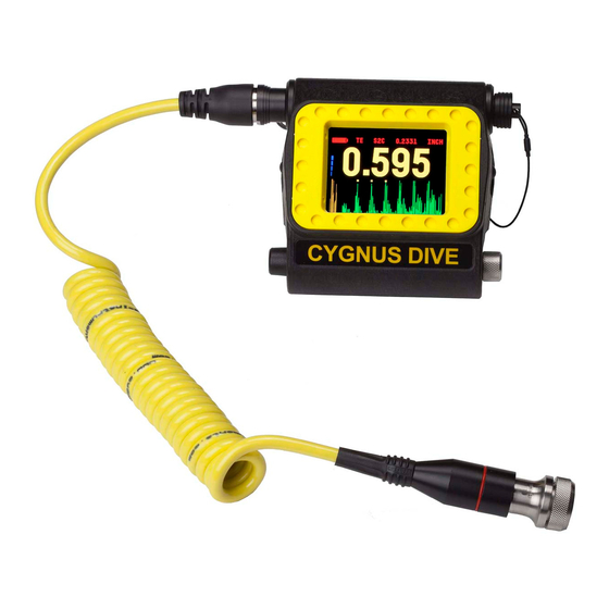
Cygnus M2-DIVE Operating Manual (118 pages)
Ultrasonic Thickness Gauge for Divers DIVE
Brand:
Cygnus
| Category:
Diving Instrument
| Size: 6.45 MB
Table of Contents
Table of Contents
3
1 Introduction
8
Cygnus DIVE Underwater Thickness Gauge
8
Cygnus Instruments
9
2 Gauge Kit Contents
10
3 The DIVE Gauge
11
Features of the DIVE Gauge
11
Fitting the DIVE Gauge
11
4 Batteries
14
Important Notes
14
Use in Hyperbaric Conditions
14
Shipping of Lithium Batteries
14
Fitting the Battery
14
Removing the Battery
15
Charging the Battery
16
5 Fitting the Ultrasonic Probe
17
Important - Cap Fitment
17
Connecting the Probe
17
Probe Calibration Check Message
18
Securing the Probe While Diving
19
6 Ultrasonic Probes (Transducers)
20
Important Notes
20
Probe Types
20
Single Element Probes
20
Twin Element Probes
21
Identifying Single or Twin Element Probes
21
Probe Identification Band
22
Probe Frequencies
22
Probe Measurement Ranges
23
Probe Selection Chart
25
Single Element Probes and Protective Membranes
26
Changing the Protective Membrane on Single Element Probes
27
Automatic Probe Type Detection
28
Twin Element Probe Wear Indication
28
7 Measure Modes
29
Multiple Echo Mode (ME)
29
Single Echo Mode (SE)
29
Echo-Echo Mode (EE)
30
Measuring Small Diameter Pipe & Tubes
31
8 Why Should I Calibrate My Thickness Gauge
32
9 Using the DIVE Gauge
33
Turning the Gauge on
33
Zeroing the Probe (Twin Crystal)
34
Turning the Gauge off
34
Before each Dive
35
The Measurement Screen
36
No Probe Connected Message
36
Low Battery Level
37
Displaying Thickness Measurements
37
The A-Scan Display
37
A-Scan Display in Single Echo Mode
38
Surface Preparation
38
Taking a Thickness Measurement
40
Measuring Small Pipe with Twin Crystal Probes
40
Signal Strength Indication
40
Echo Bars in Multiple Echo Mode
41
Stability Indication in Single Echo & Echo-Echo Modes
42
10 Interpreting the A-Scan Display in Multiple Echo Mode
43
Pits and Flaws
44
Heavy Corrosion
45
11 Interpreting the A-Scan Display in Single Echo Mode
47
Measuring over Corrosion Pits
48
12 Interpreting the A-Scan Display in Echo-Echo Mode
50
13 Changing Gauge Settings
51
The Two Button System
51
Button Functions in Menus
51
Button Functions in Setup Screens
52
Gauge Settings Saved with Probe Type
52
Displaying the Menu
53
Menu Tree Diagram
54
Data Logging Menu (DATA LOG MENU)
55
A-Scan Range Setting (A-SCAN RANGE)
55
Turning the A-Scan Display on or off (A-SCAN DISPLAY)
56
Setting the Velocity of Sound (VELOCITY)
56
Calibrating to a Known Thickness (CALIBRATE)
57
Two Point Calibration (CALIBRATE 2 POINT)
58
Ladder Step Wedge
58
Two Point Calibration Procedure
59
Zeroing the Twin Crystal Probe (ZERO PROBE)
60
Material Velocity of Sound List (MATERIAL LIST)
62
Measurement Units (UNITS)
63
Thickness Measurement Resolution (RESOLUTION)
63
Multiple Echo Mode
63
Single Echo and Echo-Echo Modes
63
Deep Coat Feature (DEEP COAT)
64
Changing the Measurement Mode (MEASURE MODE)
64
Probe Type Selection (PROBE TYPE)
65
Setting the Power Save Timer (POWER-SAVE TIMER)
65
Calibration Lock Feature
66
14 Data Logging
67
Autolog Feature
67
Grouping Measurements
68
Measurement Screen While Data Logging
68
Starting a Data Logging Session (START LOGGING)
69
Ending a Data Logging Session (STOP LOGGING)
69
Starting a New Group of Measurements (START NEW GROUP)
70
Deleting the Last Measurement (DELETE LAST)
70
Clearing the Data Logger Memory (CLEAR MEMORY)
71
Viewing the Data Logging Status (DATA LOGGER STATUS)
72
Setting the Autolog RELEASE Period (DLOG RELEASE TIME)
72
15 Helmetview Remote Display
73
Fitting the Mounting Bracket
73
16 Topside Repeater Remote Display Kit
75
Part Numbers
75
Kit Contents
75
Operation
76
Turning the Unit on
76
Turning the Unit off
76
Changing the Displayed Units
76
Display Hold Function
76
Automatic Display Backlight
76
Connecting to the DIVE Gauge
76
Testing the Link
77
Changing the Batteries
77
Topside Repeater with Video Overlay
77
Connecting the Video Signal
78
Positioning the On-Screen Display
78
17 Cyglink Surface Display and Control Kit
80
Part Numbers
80
Kit Contents
80
Connection Diagram
81
Connector Details and Signals
81
Using Cyglink with Helmetview
81
Installing Cyglink
82
Requirements
82
Upgrading
82
Installing
82
COM Port Numbers
83
Setting the COM Port Manually
83
Finding Your COM Port Number
83
Connecting to the Gauge
84
First Time USB Connection
84
Connecting the Gauge to Cyglink for the First Time
85
Connecting to the Gauge Afterwards
86
Disconnecting from the Gauge
86
Manual Connection Settings
86
Changing Gauge Settings
87
Material Velocity List
87
A-Scan Measurement Cursors
88
Using the A-Scan Cursors with Twin Crystal Probes
88
Cyglink Surveys and Data Logging
89
Editing the Survey Details
90
Editing the Survey Group Details
91
Producing a Survey Report Document
91
Transferring Data Logged Measurements from the DIVE Gauge
92
Logging Measurements Directly in Cyglink
93
Reference and Minimum Thickness Criteria
93
Pre-Set Measurement Comments List
93
Adding Comments or Notes to a Measurement
94
To Change the COM Port Number Assigned by Windows
95
Opening Device Manager
95
Cyglink Trouble Shooting
96
Connection Problems - USB Drivers
96
Wiring Problems
97
18 General Points on Thickness Gauging Using Multiple Echo Measurements
98
19 Care and Servicing
99
Cleaning the Gauge
99
Batteries
99
Environmental
99
Repairs
100
Returning the Gauge for Servicing
100
20 Replaceable Parts
101
Wrist Strap
101
Push Buttons
101
21 Spares and Accessories List
102
Ultrasonic Probes
102
Probe Spares for S*C 13Mm (½") Probes
102
Probe Spares for S*A 6Mm (¼") Probes
102
Gauge Spares
103
Accessories
103
Miscellaneous Spares
104
22 Technical Specifications
105
23 Table of Sound Velocities
108
Reading Conversions
109
24 Recycling and Disposal (EC Countries)
110
25 Shipping of Lithium-Ion Batteries
111
Battery Information
111
26 Warranty Information
112
27 Pressure Test Statement
113
28 Connection Diagram: Umbilical Cable
114
29 Connection Diagram: Umbilical to TSR
115
30 Connection Diagram: DIVE to Umbilical
116
31 Index
117
Advertisement
Advertisement
Related Products
Cygnus M3-DIVE
Cygnus MC-100
Cygnus M5-C2P
Cygnus M5-C4P
Cygnus MR400
Cygnus M5-C2
Cygnus M5-C4
Cygnus MR 500
Cygnus MINI ROV
Cygnus M5-ROV-ASCAN
Cygnus Categories
Measuring Instruments
Lighting Equipment
Monitor
Automobile Accessories
Diving Instrument
More Cygnus Manuals
Login
Sign In
OR
Sign in with Facebook
Sign in with Google
Upload manual
Upload from disk
Upload from URL