Sign In
Upload
Manuals
Brands
Curtis Manuals
Controller
1238E
Curtis 1238E Manuals
Manuals and User Guides for Curtis 1238E. We have
5
Curtis 1238E manuals available for free PDF download: Manual
Curtis 1238E Manual (158 pages)
Enhanced AC Controllers for Induction Motors and Surface Permanent Magnet Motors
Brand:
Curtis
| Category:
Controller
| Size: 1.88 MB
Table of Contents
Table of Contents
3
Figures
4
Tables
4
1 Overview
5
Curtis AC Induction Motor Controllers
5
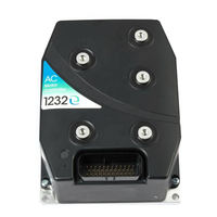
Fig. 1: Curtis 1232E/SE, 1234E/SE, 1236E/SE, 1238E Controllers
5
Getting the most out of Your Curtis Controller
6
2 Installation and Wiring
7
Mounting the Controller
7
Fig. 2A: Mounting Dimensions, Curtis 1232E/SE Controller
7
Fig. 2B: Mounting Dimensions, Curtis 1234E/SE Controller
8
Fig. 2C: Mounting Dimensions, Curtis 1236E/SE, 1238E Controllers
9
High Current Connections and Wiring Guidelines
10
Table 1 High Current Connections
10
Battery Cables (B+, B-)
11
High Current Wiring Recommendations
11
Motor Wiring (U, V, W)
11
CAN Bus (Pins 21, 23, 34, 35)
12
Low Current Wiring Recommendations
12
Position Feedback (Pins 7, 26, 31, 32)
12
Low Current Connections and Wiring Guidelines
12
Table 2: Low Current Connections
12
Controller Wiring: Basic Configuration
16
Basic Wiring Diagram, Curtis 1232E/SE, 34E/SE, 36E/SE, and 38E Motor Controllers
16
Fig. 3: Basic Wiring Diagram
16
Switch Input Wiring
17
Throttle Wiring
17
Throttle Type 2
18
Fig. 4: Wiring for Type 1 Throttles
18
Fig. 5: Wiring for Type 2 Throttles
19
Throttle Type 4
20
Fig. 6: Wiring for Type 3 Throttles
20
Throttle Type 5
21
Input/Output Specifications
22
Digital Inputs
22
Digital Input Specifications
23
Digital Input Impedance Circuits
23
Digital and PWM Outputs
24
Analog Inputs
24
Analog Inputs Specifications
25
Analog Output
25
Power Supply Outputs
25
Analog Output Specifications
25
KSI and Coil Return
26
Throttle and Brake Inputs
26
KSI and Coil Return Input Specifications
26
Throttle Input Specifications
26
Communications Ports
27
Position Feedback Input: Quadrature Encoder
27
Quadrature Encoder Input Specifications
27
Position Feedback Input: Sin/Cos Sensor
28
Sin/Cos Sensor Input Specifications
28
3 Programmable Parameters
29
Programming Menus
29
Motor Response Tuning
29
Parameter Change Faults
29
Programmable Parameter Menus: 1313 /1314 Programmer
30
Table 3: Programmable Parameter Menus
30
Electrical Frequency Constraint
33
Encoder Pulses/Revolution Constraint (Quadrature Encoder)
33
Motor Speed Constraints
33
Fig. 7 Acceleration Response Rate Diagram
37
Response Menu
37
Fig. 8 Braking Response Rate Diagram
38
Fine Tuning Menu
38
Position Hold Menu
39
Restraint Menu
39
Pump Parameters
40
Speed Limiter Menu
41
Fig. 9: Throttle Mapping, Torque Control Mode
44
Fig. 10: Effect of Gear Soften Parameter, Torque Control Mode
44
Fig. 11: Effect of Brake Taper Speed Parameter, Torque Control Mode
44
Current Limits Menu
45
Power Limiting Map Menu
46
Drive Limiting Map Menu
46
Fig. 12: Drive Current Limiting Map
46
Regen Limiting Map Menu
47
Fig. 13: Regen Current Limiting Map
47
Throttle Menu
48
Fig. 14: Throttle Adjustment
49
Brake Menu
51
EM Brake Control Menu
52
Drivers: Main Contactor Menu
54
Drivers: Proportional Driver Menu
56
Drivers: Driver 3 Menu
57
Drivers: Fault Checking Menu
58
Motor Menu
59
Motor: Control Algorithms Menu
59
Motor: 0-ACIM: Characterization Tests Menu
60
Motor: 0-ACIM: Field Weakening Control Menu
61
Motor: 0-ACIM: Swap Two Phases and Motor Type Parameters
62
Motor: 0-Acim: Los Menu
63
Motor: 1-SPM: Characterization Tests Menu
64
Motor Feedback Options
65
Motor Feedback 1-Encoder Menu
65
Motor Feedback 1-Encoder: Encoder Fault Setup Menu
66
Motor Feedback 2-Sin/Cos Menu
66
Motor Temperature Control Menu
67
Battery Menu
68
Dual Drive Menu
70
Vehicle Menu
71
Interlock Braking Menu
73
Can Interface Menu
74
Reset Controller Parameter
75
4A. MONITOR MENU
76
Table 4: Monitor Menu
76
Monitor Menu: INPUTS
78
Monitor Menu: OUTPUTS
81
Monitor Menu: BATTERY
82
Monitor Menu: MOTOR
83
Monitor Menu: CONTROLLER
84
Monitor Menu: CUTBACKS
86
Monitor Menu: MOTOR TUNING
86
Monitor Menu: VEHICLE
87
Monitor Menu: CAN STATUS
89
4B. CONTROLLER INFORMATION MENU
90
5 Initial Setup
91
Motor Temperature Sensor
92
Current Limits
92
Main Contactor
92
EM Brake
92
Motor Technology & Feedback Type
94
Faults
94
Setting Feedback Direction
94
Checking Direction of Rotation
95
Motor Characterization
95
Automated Acim Motor Characterization Procedure
97
Traction and Hydraulic Systems
97
6A. MOTOR CHARACTERIZATION: ACIM Motors
97
Motor Characterization Errors
98
Traction Systems Only
99
Hydraulic Systems Only
102
Automated SPM Motor Characterization Procedure
104
6B. MOTOR CHARACTERIZATION: SPM Motors
104
7 Tuning Guide
106
Vehicle Control Language (VCL)
110
Summary of VCL Basics
110
Variable Types
111
VCL Runtime Rates
113
I/O Control with VCL
113
Driver and Digital Outputs
114
Potentiometer Inputs
115
Interfacing the Throttle and Brake Commands
117
Throttle Processing
117
Fig. 15: VCL Motor Command Diagram
118
Brake Processing
120
Interfacing the Proportional Current Driver
121
Control Mode and Motor Control Processing
121
Fig. 16: VCL Control Mode Processing
122
Fig. 17: VCL Proportional Driver Processing
123
Using the Fault Handler in VCL
124
OEM-Defined User Faults
126
CAN Indexes for the User Fault Variables
129
Enable_Precharge()
130
VCL Function Specific to 1232E/SE, 1234E/SE, 1236E/SE, and 1238E Controllers
130
Disable_Precharge()
131
Clear_Digout()
132
Set_Digout()
132
Disable_Emer_Rev()
133
Enable_Emer_Rev()
133
Clear_Interlock()
134
Set_Interlock()
134
Setup_Pot_Faults()
135
Start_Pump()
136
Stop_Pump()
136
Automate Frequency Output
137
Diagnostics and Troubleshooting
138
Summary of LED Display Formats
139
Table 5 TYPES of LED DISPLAY
139
Table 6 TROUBLESHOOTING CHART
140
9 Diagnostics and Troubleshooting
141
10 Maintenance
149
Cleaning
149
Fault History
149
Electromagnetic Compatibility (EMC)
150
Emissions
150
Immunity
150
Electrostatic Discharge (ESD)
152
Programming Devices
155
PC Programming Station (1314)
155
Handhelf Programmer (1313)
155
Programmer Functions
155
Specifications
156
Advertisement
Curtis 1238E Manual (152 pages)
Enhanced AC Controllers for Induction Motors and Surface Permanent Magnet Motors
Brand:
Curtis
| Category:
Controller
| Size: 2.29 MB
Table of Contents
Table of Contents
2
1: Introduction
5
Features
5
Figure 1: Curtis AC Induction & SPM Motor Controllers
5
Getting the most out of Your Curtis Controller
6
2: Installation and Wiring
7
Mounting the Controller
7
Figure 2A: Mounting Dimensions, 1232E and 1232SE
7
Figure 2B: Mounting Dimensions, 1234E and 1234SE
8
Figure 2C: Mounting Dimensions, 1236E/SE and 1238E/SE
9
High Power Connections
11
Table 1 High Powered Connections
11
Low Power 35-Pin Connections
13
Table 2 Low Power Connections
14
Controller Wiring: Basic Configuration
16
Figure 3: Basic Wiring Diagram
16
Switch Input Wiring
17
Low Power Circuit Specifications
17
3: Application-Specific Features
24
Throttle Wiring
24
Figure 4: Wiring for Type 1 Throttles
24
Figure 5: Wiring for Type 2 Throttles
26
Figure 6: Wiring for Type 3 Throttles
27
Motor Speed Constraints
28
Voltage Limits
29
Battery Discharge Indicator
29
4: Programmable Parameters
30
Programming Menus
30
Table 3 Programmable Parameters Menus: 1313/1314 Programmer
31
Figure 7: Acceleration Response Rate Diagram
39
Figure 8: Braking Response Rate Diagram
40
Figure 9: Throttle Mapping (Torque Control Mode)
46
Figure 10: Effect of Gear Soften Parameter (Torque Control Mode)
46
Figure 11: Effect of Brake Taper Speed Parameter (Torque Control Mode)
46
Figure 12: Drive Current Limiting Map
48
Figure 13: Regen Current Limiting Map
49
Figure 14: Effect of Throttle Adjustment Parameters
49
Cloning Controllers
72
Table 4 Monitor Menu: 1313/1314 Programmer
73
5: Monitor Menu
73
6: Controller Information Menu
83
7: Initial Setup
84
Automated Acim Motor Characterization Procedure
89
Part 1: TRACTION and HYDRAULIC SYSTEMS
89
Part 2A: TRACTION SYSTEMS ONLY
90
Part 2B: HYDRAULIC SYSTEMS ONLY
93
Automated Spm Motor Characterization Procedure
95
9: Tuning Guide
97
Speed Mode Express Tuning
97
Speed Mode Tuning
98
Torque Mode Tuning
100
10: Vehicle Control Language (Vcl)
101
Variable Types
102
Vcl Runtime Rates
104
I/O Control with Vcl
105
Interfacing the Throttle and Brake Commands
107
Figure 15: Motor Command Diagram
109
Figure 16: Control Mode Processing
112
Interfacing the Proportional Current Driver
113
Figure 17: Proportional Driver Processing
113
Using the Fault Handler in Vcl
114
Canbus Emergency Messages
116
OEM-Defined User Faults
117
Vcl Functions Specific to 1232E/Se, 1234E/Se, 1236E/Se, & 1238E/Se Controllers
121
11: Diagnostics and Troubleshooting
133
Diagnostics
133
Summary of LED Display Formats
134
Troubleshooting
134
Table 5 Types of LED Display
134
Table 6 TROUBLESHOOTING CHART
136
12: Maintenance
144
Cleaning
144
Fault History
144
Appendix A: Vehicle Design Considerations/Emc/Esd/Recycling the Controller
145
Electromagnetic Compatibility (Emc)
145
Electrostatic Discharge (Esd)
147
Decommissioning and Recycling the Controller
147
Appendix B: En13849 Compliance
148
En13849 Compliance
148
Figure B-1: Supervisory System
148
Appendix C: Programming Devices
150
Programming Devices
150
Table D-1 SPECIFICATIONS: 1232E/SE, 1234E/SE, 1236E/SE, 1238E/SE CONTROLLERS
151
Appendix D: Controller Specifications
151
Controller Specifications
151
Curtis 1238E Manual (33 pages)
DUAL DRIVE OPERATION
Brand:
Curtis
| Category:
Controller
| Size: 1 MB
Table of Contents
Table of Contents
3
Overview
5
Fig. 1 Various Dual Drive Vehicle Configurations
5
Fig. 2A
7
Wiring
7
Fig. 2B: Basic Wiring Diagram for Master Controller
8
Fig. 2C: Basic Wiring Diagram for Slave Controller
9
Programmable Parameters
10
Table 1: Programmable Parameters Menu Table
10
Critical Angle & Inner Wheel Speed
14
Fig. 3 Typical 3-Wheel Dual Drive Vehicle Geometry
15
Fig. 4 Typical Articulated Steering Dual Drive Vehicle Geometry
15
Fig. 5: Ratio of Inner-Wheel Speed to Outer-Wheel Speed
16
Fig. 6: Inner-Wheel and Outer-Wheel Speed Maps
16
Dual Drive Setup
17
Vehicle Control Language & Can
19
Fig. 7A: Motor Command Diagram, Master Controller
20
Fig. 7B: Motor Command Diagram, Slave Controller
21
Diagnostics and Troubleshooting
23
Table 2: Troubleshooting Chart
23
Advertisement
Curtis 1238E Manual (32 pages)
Brand:
Curtis
| Category:
Controller
| Size: 0.99 MB
Table of Contents
Table of Contents
2
1: Overview
3
Figure 1 Various Dual Drive Vehicle Configurations
3
2: Wiring
4
Traction Controllers
4
Figure 2B: Basic Wiring Diagram for Manager Controller, Dual Drive Operation
5
Figure 2C: Basic Wiring Diagram for Ancillary Controller, Dual Drive Operation
6
3: Programmable Parameters
7
Table 1 Dual Drive Program Menus: 1311/1313 /1314 Programmer
7
4: Determining Critical Angle and Inner Wheel Speed
11
Figure 3: Typical 3-Wheel Dual Drive Vehicle Geometry
12
Figure 4: Typical Articulated Steering Dual Drive Vehicle Geometry
12
Figure 5: Ratio of Inner-Wheel Speed to Outer-Wheel Speed
13
Figure 6: Inner-Wheel and Outer-Wheel Speed Maps
13
5: Dual Drive Setup
14
6: Vehicle Control Language & Can
16
Figure 7A: Motor Command Diagram, Manager Controller
17
Figure 7B: Motor Command Diagram, Ancillary Controller
18
7: Troubleshooting
21
Table 2 DUAL DRIVE TROUBLESHOOTING CHART
23
Curtis 1238E Manual (30 pages)
DUAL DRIVE OPERATION
Brand:
Curtis
| Category:
Controller
| Size: 0.99 MB
Table of Contents
Table of Contents
2
1-Overview
3
Figure 1 Various Dual Drive Vehicle Configurations
3
2: Wiring
4
Figure 2A: Wiring between the Master and Slave Dual Drive Traction Controllers
4
Figure 2B: Basic Wiring Diagram for Master Controller, Dual Drive Operation
5
Figure 2C: Basic Wiring Diagram for Slave Controller, Dual Drive Operation
6
3: Programmable Parameters
7
Table 1 Dual Drive Program Menus: 1311/1313 /1314 Programmer
7
4: Determining Critical Angle and Inner Wheel Speed
11
Figure 3: Typical 3-Wheel Dual Drive Vehicle Geometry
12
Figure 4: Typical Articulated Steering Dual Drive Vehicle Geometry
12
Figure 5: Ratio of Inner-Wheel Speed to Outer-Wheel Speed
13
Figure 6: Inner-Wheel and Outer-Wheel Speed Maps
13
5: Dual Drive Setup
14
6: Vehicle Control Language & Can
16
Figure 7A: Motor Command Diagram, Master Controller
17
Figure 7B: Motor Command Diagram, Slave Controller
18
7: Troubleshooting
20
Table 2 DUAL DRIVE TROUBLESHOOTING CHART
22
Advertisement
Related Products
Curtis 1238SE
Curtis 1238
Curtis 1232E
Curtis 1234E
Curtis 1236E
Curtis 1234SE
Curtis 1236SE
Curtis 1232SE
Curtis 1239E
Curtis 1234
Curtis Categories
Coffee Maker
DVD Player
LCD TV
MP3 Player
Clock Radio
More Curtis Manuals
Login
Sign In
OR
Sign in with Facebook
Sign in with Google
Upload manual
Upload from disk
Upload from URL