Sign In
Upload
Manuals
Brands
Cub Cadet Manuals
Lawn Mower Accessories
72'' mower deck
User Manuals: Cub Cadet 72'' mower deck Lawn
Manuals and User Guides for Cub Cadet 72'' mower deck Lawn. We have
3
Cub Cadet 72'' mower deck Lawn manuals available for free PDF download: Service Manual, Owner's Manual
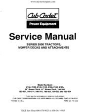
Cub Cadet 72'' mower deck Service Manual (257 pages)
2000 Series
Brand:
Cub Cadet
| Category:
Lawn Mower
| Size: 24.09 MB
Table of Contents
Safety Rules
3
Table of Contents
5
List of Illustrations
8
List of Tables
12
Safety Precautions
13
General Information
13
Reference Data
13
Chassis Serial Number Plate
13
Model 2130 Specifications
15
Model 2135 Specifications
16
Model 2140 Specifications
17
Model 2145 Specifications
18
Model 2160 Specifications
19
Model 2165 Specifications
20
Model 2185 Specifications
21
Dealer Preparation
23
Battery Activation
23
Pre-Delivery Check List
24
Preventive Maintenance
25
Lubrication Guide
25
Model 2130 Maintenance
26
Model 2130 Lubrication
27
Model 2130 Lubrication Points Diagram
28
Model 2135 Maintenance
29
Model 2135 Lubrication
30
Model 2135 Lubrication Points Diagram
31
Model 2140 Maintenance
32
Model 2140 Lubrication
33
Model 2140 Lubrication Points Diagram
34
Model 2145 Maintenance
35
Model 2145 Lubrication
36
Model 2145 Lubrication Points Diagram
37
Model 2160 Maintenance
38
Model 2160 Lubrication
39
Model 2160 Lubrication Points Diagram
40
Model 2165 Maintenance
41
Model 2165 Lubrication
42
Model 2165 Lubrication Points Diagram
43
Model 2185 Maintenance
44
Model 2185 Lubrication
45
Model 2185 Lubrication Points Diagram
46
Model 190-300 45" Mower Deck Lubrication Guide
47
Model 190-301 48" Mower Deck Lubrication Guide
48
Troubleshooting and Testing
49
Engine Start Troubleshooting
50
Electrical Circuit Troubleshooting
53
Electrical PTO Troubleshooting
55
Drive Line Troubleshooting
58
6 Speed Transmission Troubleshooting
58
Hydro Transaxle Troubleshooting
63
Brake System Troubleshooting
68
Steering Troubleshooting
69
Dash Panel and Bulkhead Troubleshooting
70
Corrective Maintenance
71
Section Use
71
Hood, Grille and Side Panels (All Models) - Removal
71
Hood, Grille, and Side Panels (All Models) Diagram
72
Hood, Grille, and Side Panels (All Models) Disassembly
73
Side Panel Removal Diagram
73
Hood, Grille, and Side Panels (All Models) Repair
74
Hood, Grille, and Side Panels (All Models) Reassembly
74
Headlight Reflector and Lens Assembly
75
Battery and Electrical Components (Models 2130, 2135, 2140, 2145, and 2185)
77
Battery and Electrical Components (Models 2130, 2135, 2140, 2145, and 2185) Diagram
78
Battery and Electrical Components (Models 2130, 2135, 2140, 2145, and 2185) Disassembly and Reassembly
79
Battery and Electrical Components (Models 2130, 2135, 2140, 2145, and 2185) Installation
80
Battery and Electrical Components (Models 2160 and 2165) Removal
81
Battery and Electrical Components (Models 2160 and 2165) Diagram
82
Battery and Electrical Components (Models 2160 and 2165) Disassembly
83
Battery and Electrical Components (Models 2160 and 2165) Inspection
84
Battery and Electrical Components (Models 2160 and 2165) Reassembly and Installation
84
PTO Clutch (Models 2130, 2135, 2140, and 2145) Removal
85
PTO Clutch (Models 2130, 2135, 2140, and 2145) Diagram
86
PTO Clutch (Models 2130, 2135, 2140, and 2145) Disassembly, Repair and Installation
87
PTO Clutch (Models 2160, 2165, and 2185) Diagram
88
PTO Clutch (Models 2160, 2165, and 2185) Removal
88
PTO Clutch (Models 2160, 2165, and 2185) Disassembly, Repair and Reassembly
89
Front Wheels (All Models) Removal, Disassembly and Reassembly
90
Rear Wheels (All Models)
91
Front Axle and Connections (All Models)
91
Front Axle and Connections (All Models) Diagram
92
Front Axle and Connections (All Models) Disassembly, Repair and Reassembly
93
Pivot Axle Limiter Bolt Adjustment
94
Seat and Seat Support Assembly (All Models)
95
Seat and Seat Support Assembly (All Models) Diagram
96
Seat Switch Removal (All Models)
97
Fender and Running Board (Models 2130, 2135, 2140 and 2145)
98
Fender and Running Board (Models 2130, 2135, 2140 and 2145) Diagram
99
Fender and Running Board (Models 2130, 2135, 2140 and 2145) Inspection, Repair, Reassembly and Installation
100
Fender and Runnig Board (Models 2160, 2165 and 2185)
101
Fender and Runnig Board (Models 2160, 2165 and 2185) Diagram
102
Dash Panel, Bulkhead and Engine Controls (All Models)
104
Dash Panel, Bulkhead and Engine Controls (All Models) Diagram
105
Steering Assembly (All Models)
107
Steering Assembly (All Models) Diagram
108
Aligning Steering Gear with Lower Steering Arm
110
Implement Lift Handle (All Models)
111
Implement Lift Hanger (All Models)
114
Implement Lift Hanger (All Models) Diagram
115
Fuel Tank (All Models)
116
Fuel Tank (All Models) Diagram
117
Control Pedals and Brake Linkage (All Models)
118
Control Pedals and Brake Linkage (All Models) Diagram
119
Six Speed Transmission Controls (Models 2130, 2140 and 2160)
123
Six Speed Transmission Controls (Models 2130, 2140 and 2160) Diagram
124
Hydro Transmission Controls (Models 2135, 2145, 2165 and 2185)
126
Hydro Transmission Controls (Models 2135, 2145, 2165 and 2185) Diagram
127
Drive Line (Models 2130, 2140 and 2160)
130
Drive Line (Models 2130, 2140 and 2160) Diagram
131
Drive Line (Models 2135, 2145, 2165 and 2185)
133
Clutch Assembly, Control Arm, and Interlock Linkage (Models 2130, 2140 and 2160)
136
Clutch Assembly (Models 2130, 2140 and 2160)
138
Hydrostatic Transmission, Neutral Linkage, and Hydraulic Lines (Models 2135, 2145, 2165 and 2185)
142
Hydrostatic Transmission, Neutral Linkage, and Hydraulic Lines (Models 2135, 2145, 2165 and 2185) Diagram
143
Hydrostatic Transmission (Models 2135, 2145, 2165 and 2185)
145
Hydrostatic Transmission (Models 2135, 2145, 2165 and 2185) Installation
150
Transaxle Removal (All Models)
152
Blocking the Deck Diagram
152
Transaxle Disassembly (All Models)
153
Transaxle Removal (All Models) Diagram
154
Brake Assembly (All Models)
156
Axle Housing and Axle Assemblies (All Models)
158
Axle Housing and Axle Assemblies (All Models) Diagram
159
Six-Speed Transaxle (Models 2130, 2140 and 2160)
160
Six-Speed Transaxle (Models 2130, 2140 and 2160) Diagram
161
Interlock Shift Assembly (Models 2130, 2140 and 2160)
163
Differential Gear Assembly
164
Shift Shaft Assembly (Models 2130, 2140 and 2160)
165
Installing Shift Keys (Models 2130, 2140 and 2160)
167
Hydrostatic Transaxle (Models 2135, 2145, 2165 and 2185)
171
Hydrostatic Transaxle (Models 2135, 2145, 2165 and 2185) Diagram
172
Differential Gear Assembly Diagram
173
Engine and Muffler Removal (All Models)
176
Engine Control Cables (Model 2185) Diagram
177
Wire Harness Connections (Model 2185) Diagram
177
Engine and Muffler Mounting (Models 2130, 2135, 2140 and 2145)
178
Engine and Muffler Mounting (Models 2160, 2165 and 2185)
179
Frame (All Models)
181
Frame and Attachments (All Models) Diagram
182
38-Inch Mower Deck (Tractor Models 2130 and 2135)
183
Deck and Attachments (Models 2130 and 2135) Diagram
184
Deck Drive Components (Models 2130 and 2135)
185
42-Inch Mower Deck (Models 2140 and 2145)
190
Deck and Attachments (Models 2140 and 2145) Diagram
191
Deck Drive Components (Models 2140 and 2145) Diagram
193
46-Inch Mower Deck (Model 190-300)
197
Deck and Attachments (Model 190-300 Mower Deck) Diagram
198
Deck Drive Components (Model 190-300 Mower Deck) Diagram
199
48-Inch Mower Deck (Model 190-301)
205
Deck and Attachments (Model 190-301 Mower Deck) Diagram
207
Deck Drive Components (Model 190-301 Mower Deck) Diagram
209
Mower Deck Spindle Assembly (All Models)
215
Blade Spindle Assembly (All Mower Decks) Diagram
215
Hand Packing Bearing Cones with Grease
217
Adjustments
219
Hood and Grille (All Models) Adjustment
219
PTO Clutch Burnishing Procedure (All Models)
219
Adjusting the PTO Clutch (Models 2160, 2165 and 2185)
219
Front Pivot Axle Adjustment (All Models)
220
Front Wheel Alignment (All Models)
220
Adjusting Lift Assist Spring Tension (All Models)
221
Brake Adjustment - All Models
222
Brake Connections Diagram
222
Clutch Adjustment Rod - AGS Six Speed Tractors (Models 2130, 2140 and 2160)
223
Hydro Adjustment Rod - HDS Hydrostatic Tractors (Models 2135, 2145, 2165 and 2185)
223
Adjustment Rod Connections Diagram
224
Shift Interlock Rod Asjustment - AGS Six Speed Tractors (Models 2130, 2140 and 2160)
224
Hydro Stop Rod Adjustment - HDS Hydrostatic Tractors (Models 2135, 2145, 2165 and 2185)
224
Neutral Adjustment - AGS Six Speed Tractors (Models 2130, 2140 and 2160)
225
Neutral Adjustment - HDS Hydrostatic Tractors (Models 2135, 2145, 2165 and 2185)
226
Throttle Cable Adjustment (All Models)
227
Choke Cable Adjustment (All Models)
227
Throttle and Choke Cable Connections (Models 2130, 2135, 2160 and 2165) Diagram
227
Attachments
229
38 And 42 Inch Mulching Attachments (Models 190-314 and 190-315)
229
Mulching Kit Components Diagram
229
Deck Removal from Tractor
230
Remove Cutting Blades from Deck
230
Loosen Hex Nut Securing Cutting Blade
230
Assemble Mulching Baffle
231
Seating the Baffle Assembly
232
Installing Blades and Hardware
232
Using Pilot Holes to Align Blades
233
42 Inch Spring Trip Blade (Model 190-302)
233
Tractor Preparation
233
42 Inch Spring Trip Blade Components Diagram (Model 190-302)
234
Removing Front Bumper
235
Installing the Lift Bracket
235
Attaching Handle Support Tube
235
Installing Blade Pivot Handle
235
Routing Pivot Release Cable
236
Attaching Trigger to Cable
236
Inserting Flat Weld Nut
236
Installing Trigger Assembly
236
Blade Installation
237
Installing Tie Straps
237
Attaching Lift Rod to A-Frame
237
Loosen Front Support Plate
237
Blade Adjustments
238
Installing Hitch Assembly
238
Attaching Adjustment Rod to Lift Bracket
238
40 Inch Snow Thrower Attachment (Model 190-303)
239
Removing Front Bumper Diagram
240
Installing Frame Mtg. Brackets
240
Snow Thrower Assembly Preparation
240
Installing Discharge Chute
241
Installing Chute Crank Support Tube and Tilt Handle
241
Install Chute Crank Rod
241
Attaching Chute Crank Rod
241
Inserting Flat Weld Nut Diagram
242
Installing Trigger Assembly Diagram
242
Installing Snow Thrower Lift Handle and Latch Release Cable
242
Snow Thrower Installation
243
Attaching Snow Thrower to Tractor Frame
243
Snow Thrower Maintenance
244
Attaching Double Pulley Subframe Assembly
244
Positon Flat Idler Pulley
244
Shave Plate and Skid Shoes
245
Removing Belt Guide
245
Remove PTO Drive Belt
245
28 Inch Rear Mounted Tiller (Model 190-304)
246
Removing Auger Belt from Snow Thrower
246
Stand Snow Thrower on Auger Housing Diagram
246
28 Inch Rear Mounted Tiller Components Diagram (Model 190-304)
247
Installing Lift Cylinder Mounting Bracket
248
Marking Location for Holes
248
Marking Hole Location for Electric Lift Switch
249
Installing Lift Switch
249
Tiller Assembly Preparation
250
Install Left Channel Bracket Assembly
250
Install Lift Arm and Spacers
250
Install Right Channel Bracket
250
Attaching Helper Springs
251
Installing Idler Shaft and Bracket
251
Securing Idler Shaft
251
Installing Roll Pin
251
Tiller Installation
252
Routing the PTO Belt
252
Installing V-Idler Pulley
252
Proper PTO Belt Routing
252
Attaching Tiller to Tractor
253
Attaching Lift Cylinder to Tractor
253
Attaching Lift Cylinder to Tiller
253
Installing Extension Spring
254
Install PTO Belt on PTO Clutch
254
Tiller Maintenance
255
Place PTO Belt in Front Idler Pulleys
255
Correct PTO Belt Routing
255
Lubricating Right Bearing Cup
256
Tiller Tines Diagram
256
Advertisement
Cub Cadet 72'' mower deck Service Manual (289 pages)
with mower decks and attachments
Brand:
Cub Cadet
| Category:
Tractor
| Size: 28.78 MB
Cub Cadet 72'' mower deck Owner's Manual (49 pages)
72" mower deck for tractor models 7230; 7270
Brand:
Cub Cadet
| Category:
Lawn Mower Accessories
| Size: 0.81 MB
Advertisement
Advertisement
Related Products
Cub Cadet THE TANK M48
Cub Cadet M466
Cub Cadet M46E
Cub Cadet THE TANK M60
Cub Cadet THE TANK M72
Cub Cadet M465
Cub Cadet Tank M60-KH
Cub Cadet Tank M54-KH
Cub Cadet M46F
Cub Cadet MX 550
Cub Cadet Categories
Lawn Mower
Tractor
Snow Blower
Trimmer
Utility Vehicle
More Cub Cadet Manuals
Login
Sign In
OR
Sign in with Facebook
Sign in with Google
Upload manual
Upload from disk
Upload from URL